Lightweight, conformal, wideband airframe antenna

a wideband, conformal technology, applied in the direction of resonant antennas, toys, toys, etc., can solve the problems of low efficiency trailing wires, small and heavy ferrite-loaded loop antennas with inadequate rf performance, weight, cabling and maintenance problems, etc., to achieve a wideband and increase directivity

Inactive Publication Date: 2008-07-17
APPLIED RADAR
View PDF13 Cites 13 Cited by
  • Summary
  • Abstract
  • Description
  • Claims
  • Application Information

AI Technical Summary

Benefits of technology

[0009]It is, therefore, the object of this invention to provide a microwave antenna constructed from lightweight and strong textile materials by textile technology means.
[0014]It is a further object of this invention to provide a small aircraft conformal antenna capable of providing vertical and horizontal polarization performance.
[0019]In the primary embodiment of this application, metalized or conductive fabric is arranged as either a dipole or monopole antenna over the wings, tail assembly or fuselage of a SUAV. The metalized or conductive fabric is either applied directly to the airframe or is stitched, glued or otherwise attached the fabric covering the airframe, connected to a transmitter, receiver or transceiver and a sealant or epoxy is applied to the antenna to provide strengthening to the fabric. One or more parasitic elements of conductive or metalized fabric are placed adjacent to the conductive element to provide increased directivity or broader bandwidth.

Problems solved by technology

There are no small, lightweight, conformal antennas with adequate RF performance.
There are low efficiency trailing wires and very small and heavy ferrite-loaded loop antennas with inadequate RF performance.
The current method of providing such an antenna capability is to attach many antennas to the aircraft with resulting weight, cabling and maintenance problems.

Method used


Image

  • Lightweight, conformal, wideband airframe antenna
  • Lightweight, conformal, wideband airframe antenna
  • Lightweight, conformal, wideband airframe antenna

Examples


Embodiment Construction

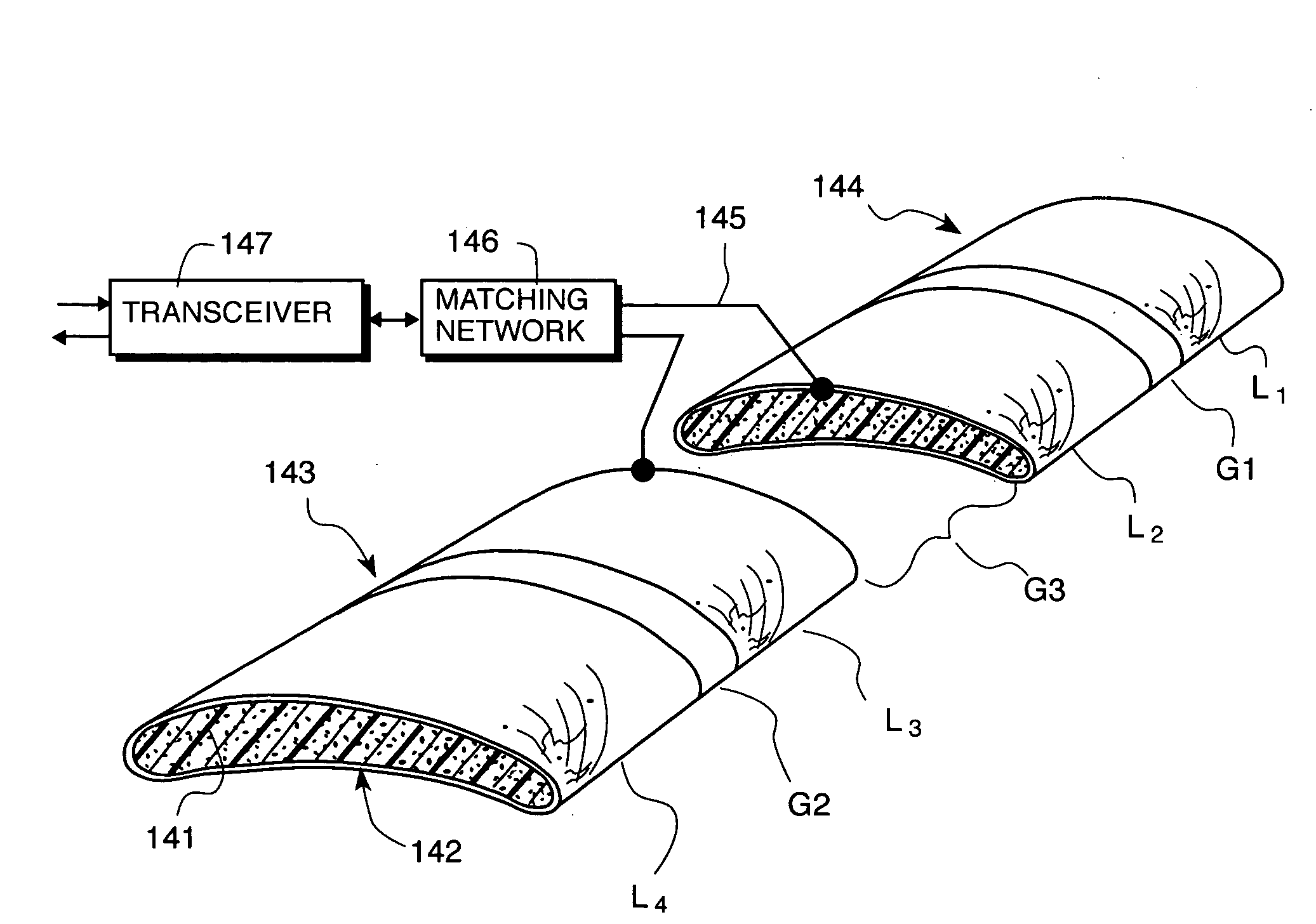
[0036]The preferred embodiment of this invention is a lightweight, broadband conformal antenna. There are several elements in the construction of this type of antenna. First, is the initial design of the antenna which the inventors achieved by using a scaled truss airframe construction with scaled motors to determine the shape, separations of panels and wiring of the antenna. The second element is the testing of the antennas in an anechoic chamber to evaluate beam patterns and performance. A third element is to evaluate different conductive fabrics with regards to their suitability in an aeronautical environment. The final elements are the attachment to the airframe, and the sealing of the conductive fabric if needed. The design of the broadband antenna is discussed first.

1.0 Design of Wideband Conformal Antennas Integrated with an Airframe

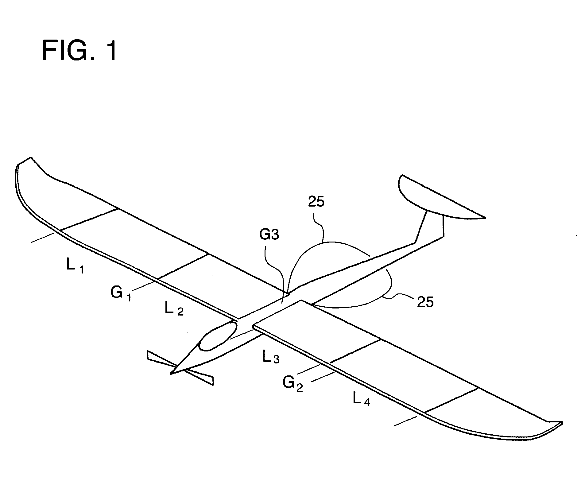
[0037]In this application a conformal antenna in FIG. 1 is comprised of four separate segments, but each segment is constructed by means of condu...


PUM


Abstract

A conformal antenna comprising: an electrically neutral airframe; metalized fabric covering said airframe; and transmission lines attached to said metalized fabric to connect to a transceiver.

Description

FIELD OF THE INVENTION[0001]This invention relates to a novel wideband conformal antenna and methods for constructing such.BACKGROUND OF THE INVENTION[0002]Wideband conformal antennas are of much interest to the aircraft manufacturing community since they allow a lower drag replacement for the multiplicity of antennas currently employed on aircraft constructed according to the current art.[0003]In the past, antenna systems have been after-thought appendages to existing aircraft. Following another paradigm to produce optimal performance, this invention uses airframe embeddable technology to provide conformal load bearing antenna structures (CLAS) during airframe design.[0004]Current methods of producing conformal antennas are based on the composite construction found on heavily wing-loaded, high speed aircraft. There is however a need for small, low speed aircraft that have a long endurance. These same aircraft are required to have wideband antennas to support on-board systems such a...

Claims


Application Information

Patent Timeline
Patent Type & Authority Applications(United States)
IPC IPC(8): H01Q1/28
CPCA63H27/02H01Q1/287H01Q5/00H01Q5/357H01Q9/40H01Q5/25H01Q9/28
Inventor DEAETT, MICHAEL A.WEEDON, WILLAM H.HAUCK, BRYAN L.
Owner APPLIED RADAR
Why Eureka
Try Eureka