Dual cutter router bit

a router bit and router bit technology, applied in the field of woodworking, can solve the problem that the embodiment lacks any projection beyond the lower part of the embodimen

Inactive Publication Date: 2008-07-17
HILKER DAVID
View PDF17 Cites 33 Cited by
  • Summary
  • Abstract
  • Description
  • Claims
  • Application Information

AI Technical Summary

Benefits of technology

[0031]The present router bit comprises a shaft supporting a pair of cutters longitudinally separated in fixed mutual displacement by an intermediary structure. In some embodiments, the intermediary structure comprises or supports a third cutter. Certain embodiments provide means for separating components of the router bit, e.g., for replacement or maintenance. In many embodim

Problems solved by technology

However, all embodiments lack any projection beyond the lower cutter, othe

Method used


Image

  • Dual cutter router bit
  • Dual cutter router bit
  • Dual cutter router bit

Examples


first embodiment

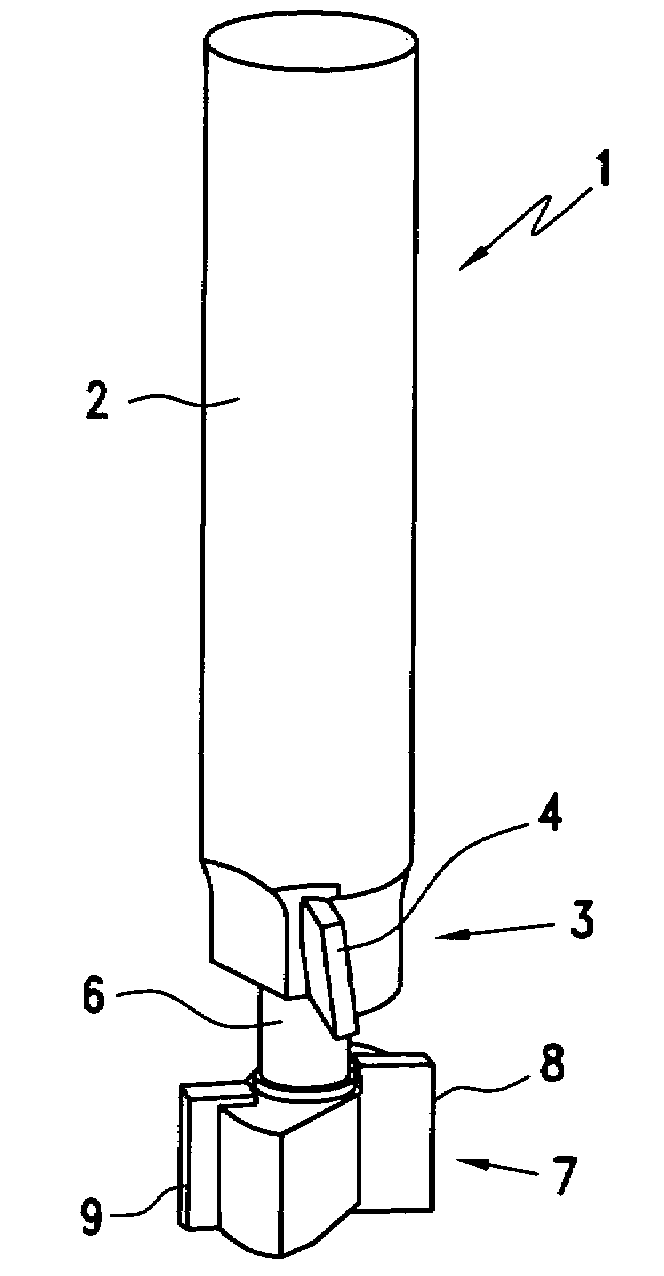
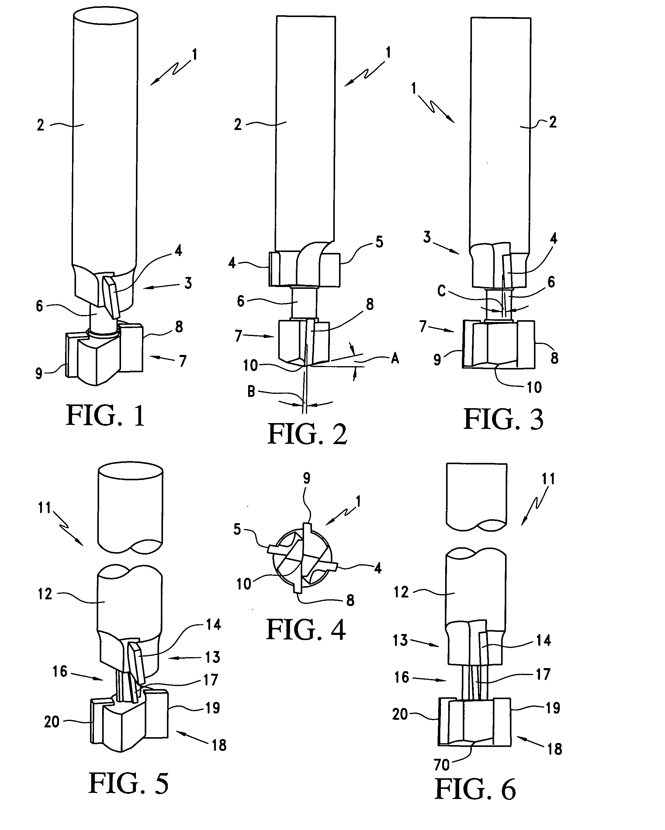
[0061]Referring to FIG. 1, the router bit 1 of the invention comprises a longitudinally-extending principal shaft 2, below which is an upper cutter 3, from which an upper left blade 4 radially projects, as shown. The upper right blade 5 (see, e.g., FIG. 2) projects radially from the principal shaft in the opposite direction from that of the upper right blade. Longitudinally displaced below the upper cutter at a rigidly fixed distance is a lower cutter 7, comprising a lower right blade 8 and a lower left blade 9 (see, e.g., FIG. 3), projecting radially in opposite directions. The upper cutter and the lower cutter are separated by an intermediary shaft 6, whose diameter is less than that of the principal shaft for reasons that will be explained. The lower cutter is positioned in proximity to, and below, the lower end of the intermediary shaft.

[0062]It will readily be seen that in the embodiments shown in FIGS. I to 18, the various blades are “wing blades,” i.e., they are essentially r...

second embodiment

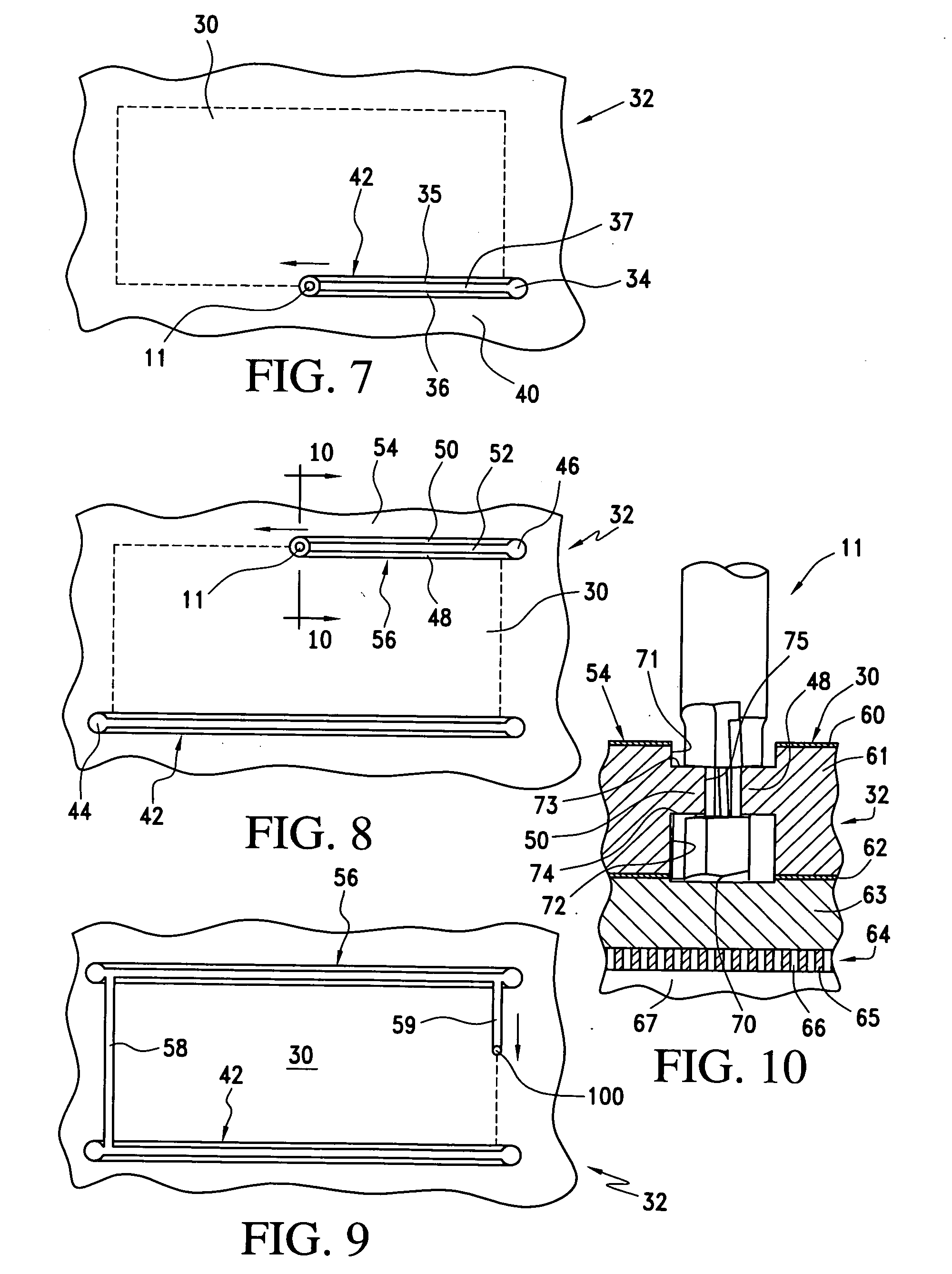
[0074]FIG. 8 shows the next step in this Here, the entire initial separation 42 has been cut between the principal work piece 30 and first adjacent work piece 40, with tenons cut into the facing edges of each of these parts, as described. The second router bit 11 is then removed from the work piece at terminal hole 44 and moved to a position diagonally opposite that position, to cut the second initial hole 46, initiating creation of the secondary separation 56. As with all of these nested based process steps, this procedure is likewise automated by conventional CNC programming. After having cut the second initial hole, the router bit is moved along the direction of the arrow shown in FIG. 8 to create the secondary separation 56. In this process, the second principal tenon 48 is cut into the principal part on the opposite edge of that part from the first principal tenon 35. I.e., in this example the final part will have tenons on opposite edges. Of course, in other applications, ten...

third embodiment

[0099]Referring, now, to FIGS. 19 and 20, we see that the router bit comprises an upper shaft 112 with an upper spiral cutter 113 incorporated into the lower end of the upper shaft. The upper spiral cutter incorporates a first upper spiral 114 and, on the opposite side of the upper spiral cutter, a second upper spiral 115 (see, e.g., FIG. 20). The first upper spiral cutter includes a first upper spiral cutting edge 116, and the second upper spiral 115 includes a second upper spiral cutting edge 117. It will be noted that when this router bit is rotated clockwise, i.e., from the configuration shown in FIG. 19 to the configuration shown in FIG. 20, the bit will tend to force the upper surface of the work piece downward. Accordingly, the upper spiral cutter may be referred to as a down cut spiral.

[0100]Of course, each of the two spirals 114 and 115 includes appropriate support material to provide structural integrity for high speed operation. This is conventional and will not be descri...


PUM


Abstract

The router bit includes an upper and a lower cutter, axially aligned and separated by a fixed longitudinal displacement. No substantial portion of the bit extends beyond the lower end of the lower cutter. In some embodiments, the lower cutter may be configured with bottom face blades to allow the router to be used as a plunging bit. The cutters may use wing blades or spiral blades. The portion of the bit intervening between the upper and lower cutters may also be configured as a cutter. In some embodiments, the router bit is integral. In other embodiments, it comprises separate elements that may be axially secured.

Description

BACKGROUND OF THE INVENTION[0001]1. Field of the Invention[0002]This invention relates to the field of woodworking and, in particular, cabinet making.[0003]2. Description of Prior Art[0004]Skilled craftsmen have built fine cabinetry since the dawn of history. Over the millennia, steady improvements in cabinet design and execution have transformed what originally was merely utilitarian manufacture into a recognized and admired art form. Museums, everywhere, display superb examples of the cabinetmaker's art, and examples of Seventeenth and Eighteenth Century cabinets and other furniture pieces from noted artists often command huge prices at auction.[0005]However, development of the structural aspects of cabinetmaking has not entirely kept pace with the skill of woodworkers and the exacting artistic and decorative requirements of those willing to pay substantial sums for their finest products. Crudely made cabinets, often seen installed in kitchens and closets, commonly utilize simple ...

Claims


Application Information

Patent Timeline
IPC IPC(8): B27G13/12B23C5/12B26D1/12B23C3/12
CPCB23C5/1054B23C2210/02Y10T407/1948B27G13/14B27G13/005
Inventor HILKER, DAVID
Owner HILKER DAVID
Why Eureka
Try Eureka