Minimally Invasive Interbody Device Assembly

a technology of interbody device and assembly, which is applied in the field of minimally invasive interbody device assembly, can solve the problems of reducing the height of the collapsed disc space, and reducing the efficiency of the surgery

Inactive Publication Date: 2008-07-17
THOMPSON MIS
View PDF75 Cites 91 Cited by
  • Summary
  • Abstract
  • Description
  • Claims
  • Application Information

AI Technical Summary

Benefits of technology

[0011]In accordance with the teachings of the present invention, a minimally invasive interbody device assembly is disclosed that includes an interbody device that restores the disc space height between two vertebrae and an instrument detachably coupled to the interbody device for positioning the device in the disc space and delivering bone graft material to the disc space that is distributed on both sides of the interbody device. The interbody device includes a relatively narrow configuration in one dimension and a relatively wide configuration in an opposite dimension. After the disc space has been cleared, the device is inserted into the disc space using the instrument in a direction so that the wide dimension of the device is substantially parallel to the body of the vertebra

Problems solved by technology

However, known cage designs are limited in that they only allow for partial filling of the interbody space where the graft material is maintained within the cage, thus only allowing partial fusion between the vertebrae.
Further, the known bone graft cages are difficult to place because of their square or cylindrical shape, and put the nerve roots at risk during the procedure, sometimes resulting in retraction or direct nerve root injury.
Also, the known cages do not allow the collapsed disc space height to be fully restored in that they cannot distract the open disc space once they are in place.
This can result in the surg

Method used


Image

  • Minimally Invasive Interbody Device Assembly
  • Minimally Invasive Interbody Device Assembly
  • Minimally Invasive Interbody Device Assembly

Examples


Embodiment Construction

[0036]The following discussion of the embodiments of the invention directed to a minimally invasive interbody device assembly including an interbody device and an instrument for positioning the device and delivering bone graft material to the disc space is merely exemplary in nature, and is in no way intended to limit the invention or its applications or uses.

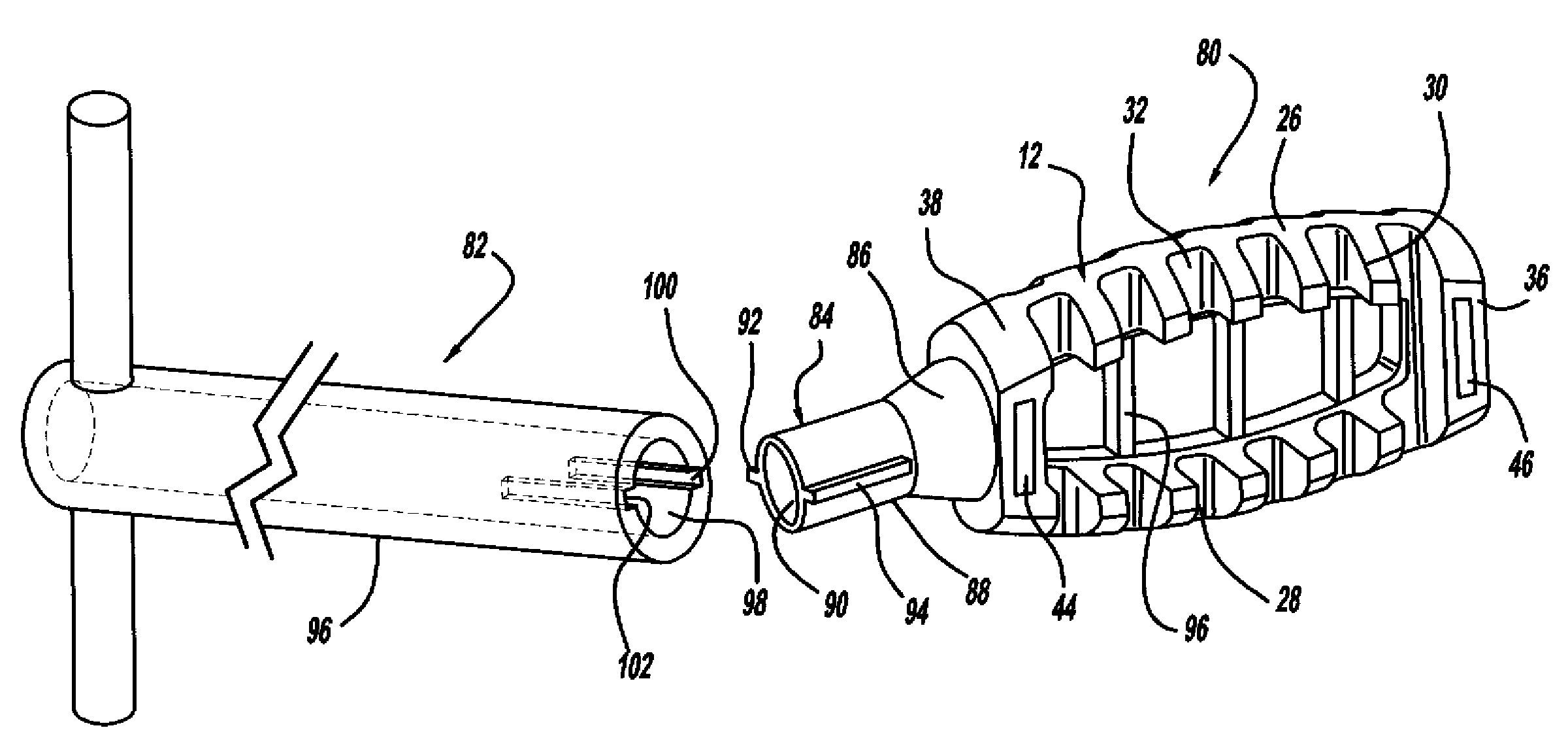
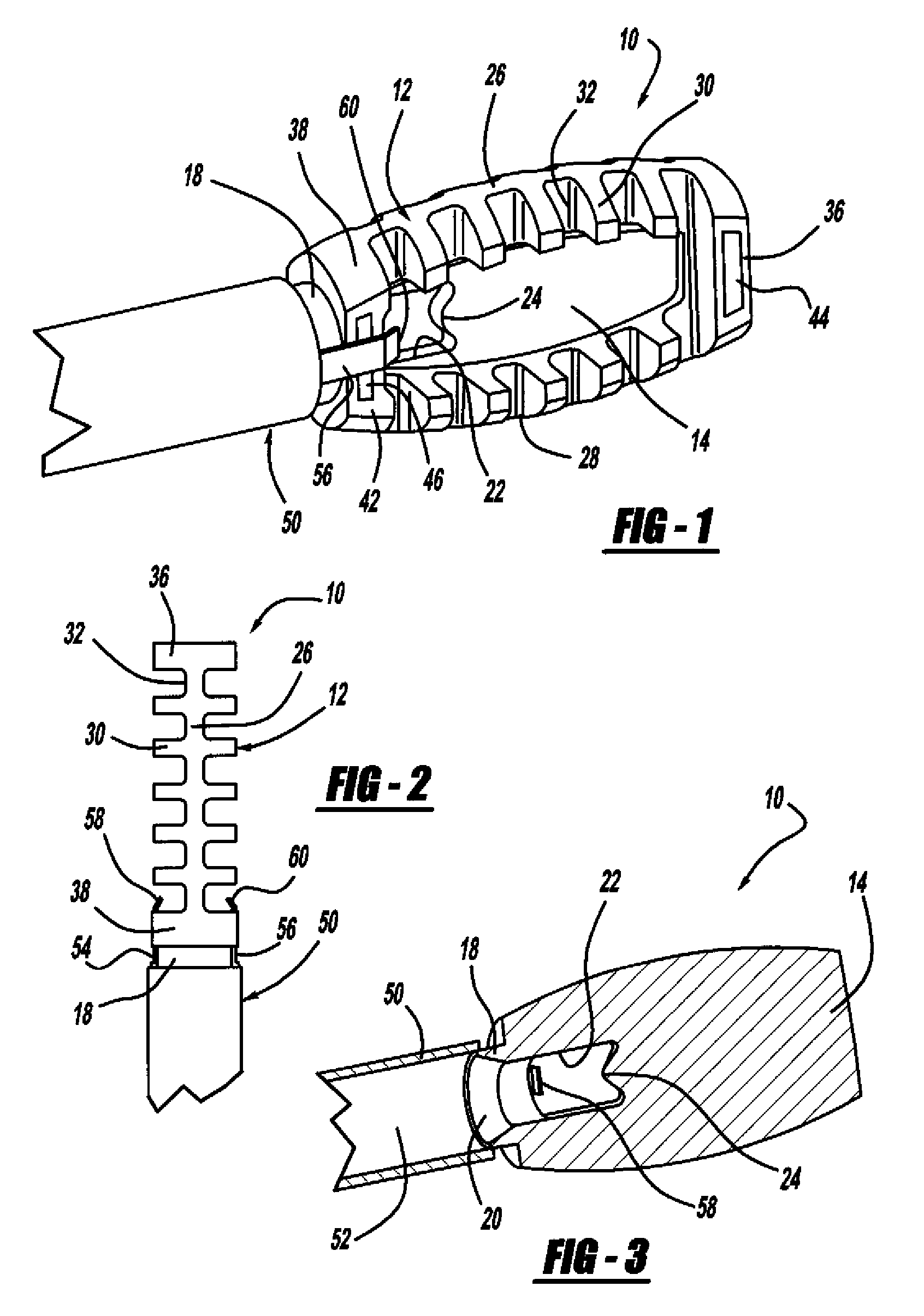
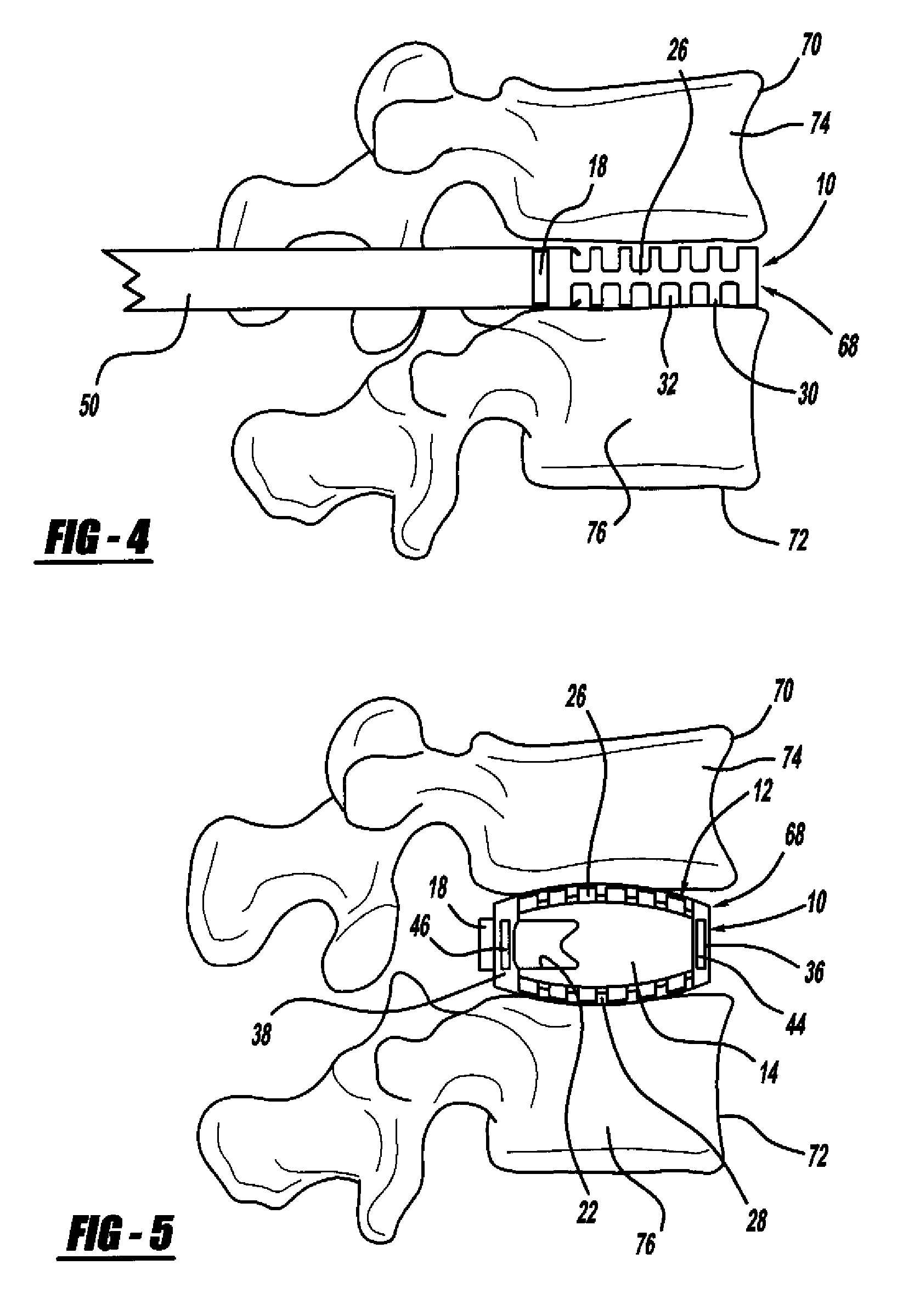
[0037]FIG. 1 is a perspective view, FIG. 2 is a top view and FIG. 3 is a cross-sectional view of a minimally invasive interbody device 10 that is to be positioned within the interbody disc space between two vertebral bodies once the disc has been removed as part of a spinal fusion surgical procedure. As will be discussed in detail below, the device 10 operates to restore the disc space height that has been lost by age or damage and may be causing pain as a result of nerve pinching, as discussed above. Additionally, the device 10 facilitates the distribution of bone graft material within the disc space.

[0038]The interbody device...


PUM


Abstract

A minimally invasive interbody device assembly that includes an interbody device that restores the disc space height between two vertebrae and an instrument detachably coupled to the interbody device for positioning the device in the disc space and delivering bone material to the disc space that is distributed on both sides of the interbody device. The device is inserted into the disc space using the instrument in a direction so that the wide dimension of the device is substantially parallel to the body of the vertebrae. The device is then rotated by the instrument so that the wide dimension of the device becomes perpendicular to the vertebral body so as to cause the disc space height to be restored. Bone graft material is then forced down the instrument so that the bone graft material is distributed on both sides of the device. The instrument is then detached from the device.

Description

CROSS-REFERENCE TO RELATED APPLICATIONS[0001]This application is a continuation-in-part application of U.S. patent application Ser. No. 11 / 623,356 filed Jan. 16, 2007, titled “Minimally Invasive Interbody Device.”BACKGROUND OF THE INVENTION[0002]1. Field of the Invention[0003]This invention relates generally to an interbody device assembly for inserting an interbody device between two vertebrae during spinal fusion surgery and, more particularly, to a minimally invasive interbody device assembly that includes an interbody device for restoring the disc space height between two adjacent vertebrae during minimally invasive spinal fusion surgery, and an instrument for positioning the device in the disc space and delivering bone graft material to the disc space on both sides of the device.[0004]2. Discussion of the Related Art[0005]The human spine includes a series of vertebrae interconnected by connective tissue referred to as discs that act as a cushion between the vertebrae. The discs...

Claims


Application Information

Patent Timeline
IPC IPC(8): A61F2/44A61B17/58
CPCA61B2017/0256A61F2310/00023A61F2/447A61F2/4601A61F2/4611A61F2002/3008A61F2002/30166A61F2002/30235A61F2002/30367A61F2002/30426A61F2002/3082A61F2002/4627A61F2002/4629A61F2220/0025A61F2220/0033A61F2230/0028A61F2230/0069A61F2250/0098A61F2/4455
Inventor PEREZ-CRUET, MIGUELANGELO J.PEPPER, JOHN R.
Owner THOMPSON MIS
Why Eureka
Try Eureka