Solar cells for stratospheric and outer space use

a technology for stratospheric and outer space, applied in the field of solar cells, can solve the problems of satellite communication system capacity limitations, increasing challenges for high-capacity wireless services, and not being serious about the harsh, damaging environment in which these solar cells will be used

Inactive Publication Date: 2008-07-24
UNITED SOLAR OVONIC
View PDF8 Cites 46 Cited by
  • Summary
  • Abstract
  • Description
  • Claims
  • Application Information

AI Technical Summary

Benefits of technology

[0007]The present invention comprises a photovoltaic device adapted for use in a stratospheric or outer space environment. The photovoltaic device includes a substrate and at least one solar cell deposited on the substrate. It further includes a protective coating deposited over and completely encapsulating the one solar cell. The protective coating: a) does not deleteriously affect the photovoltaic- properties of the solar cell; b) is formed of a material which protects said solar cell from the harsh conditions in the atmospheric, stratospheric or outer space environment in which the photovoltaic device is adapted to be used; and c) remains substantially unchanged when exposed to the harsh conditions in the atmospheric, stratospheric or outer space environment in which the photovoltaic device is adapted to be used. Preferably the protective coating is a coating of a silicone based material, such as a spray deposited coating of a silicone based material. The protective coating is between 0.01 and 2 mil thick, more preferably between 0.2 and 2 mil thick, even more preferably between 0.5 and 2 mil thick, and most preferably between 1 and 2 mil thick.

Problems solved by technology

In this regard, the demand for high-capacity wireless services is bringing increasing challenges.
Terrestrially, the need for line-of-sight electromagnetic propagation paths represents a constraint unless very large numbers of base-station masts are deployed, and satellite communication systems have capacity limitations.
There has not however been any serious consideration as to the harsh, damaging environments in which these solar cells will be used.
In short, there has not been much consideration of how to protect the solar cells from the harmful effects of the stratospheric and outer space environments.

Method used


Image

  • Solar cells for stratospheric and outer space use
  • Solar cells for stratospheric and outer space use
  • Solar cells for stratospheric and outer space use

Examples


Embodiment Construction

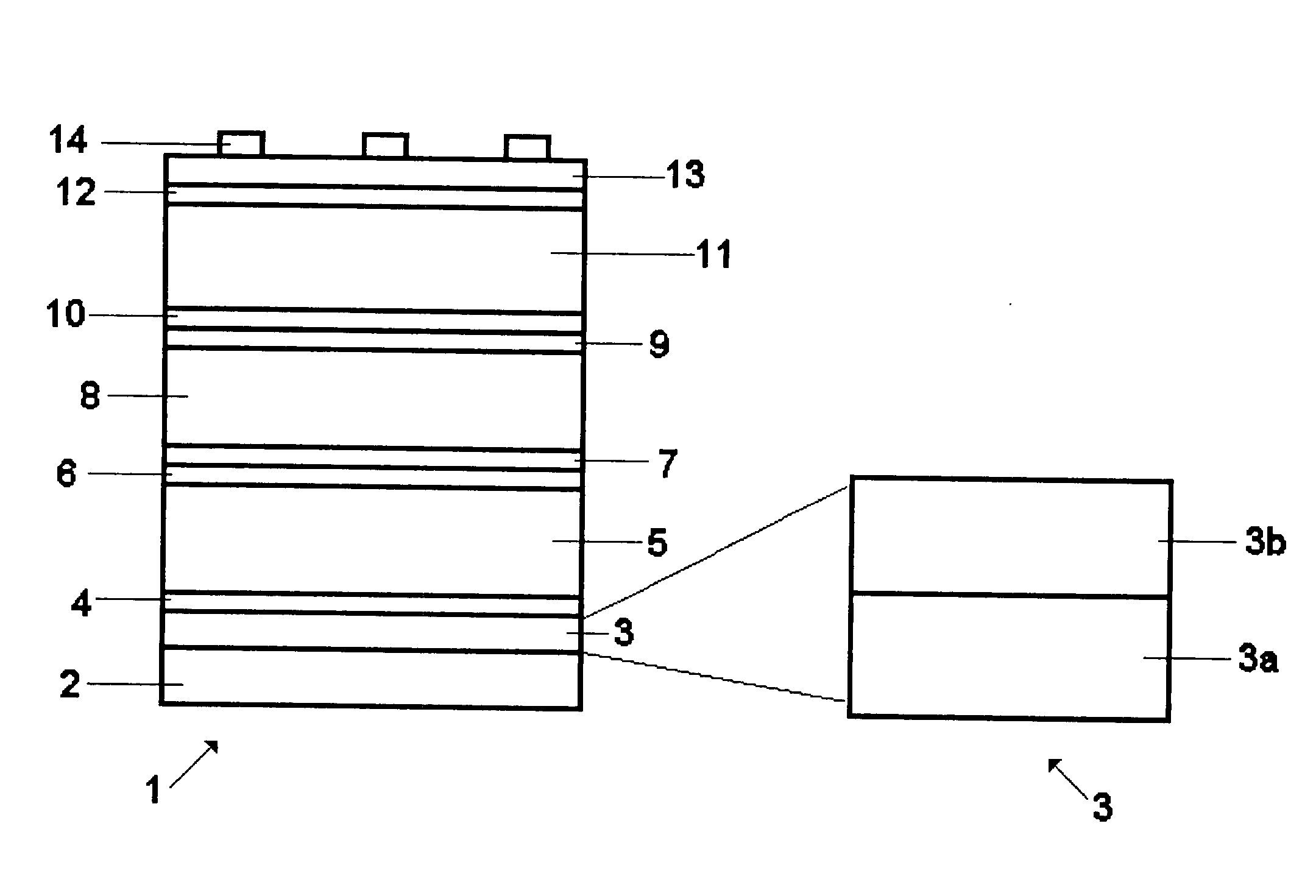
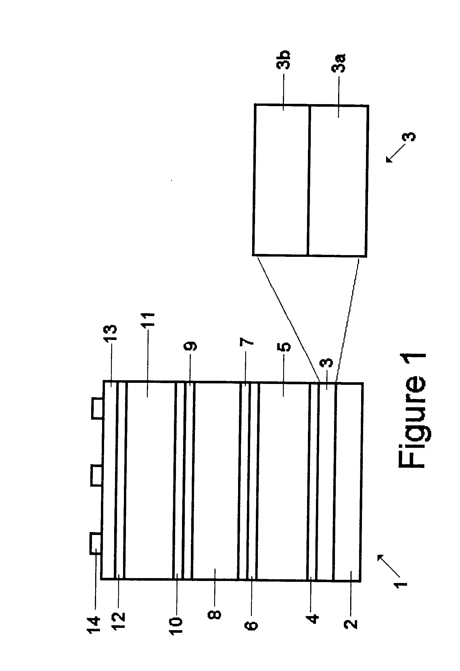
[0019]The present invention comprises encapsulated thin film amorphous silicon alloy solar cells on stainless steel or polymer substrates for satellite and airship applications. The encapsulant layer provides a protective coating on the photovoltaic devices. The encapsulant layer is transparent, flexible, space compatible, and mechanically hard. Also, the coating adheres well to the construction materials of the photovoltaic cells and is a barrier to atmospheric contaminants. Due to the different environments in the stratosphere and space, the encapsulant material must meet many stringent requirements.

[0020]The encapsulant coating must accomplish two objectives: 1) protection of the photovoltaic device; and 2) control of the absorptivity and emissivity of the cell. With regard to the first objective, the encapsulant coating will offer protection from: a) terrestrial environmental factors such as humidity and atmospheric contaminants; b) mechanical handling during module / array fabric...


PUM


Abstract

A light weight photovoltaic device for use in stratospheric and outer space applications. The device includes a protective surface coating on the light incident side thereof. The protective coating does not deleteriously affect the photovoltaic properties of the solar cell, is formed of a material which protects said solar cell from the harsh conditions in the stratospheric or outer space environment in which the photovoltaic device is adapted to be used; and remains substantially unchanged when exposed to the harsh conditions in the stratosphere or outer space. The protective coating is preferably made of a spray coated silicone based material and is between 0.01 and 2 mil thick.

Description

GOVERNMENT LICENSE RIGHTS[0001]This invention was made with Government support under U.S. Air Force Contract number F29601-03-C-0122. The Government has certain rights in this invention.FIELD OF THE INVENTION[0002]The present invention relates to solar cells for use in the stratosphere on airships and in outer space on spacecrafts. More specifically, the present invention relates to light weight solar cells (specific power: >500 W / kg) and ultralight solar cells (specific power: >1000 W / kg) deposited on polymer or thin metallic films, and including spray coated silicone encapsulants deposited on the top thereof for protection against the atmospheric, stratospheric and outer space environments.BACKGROUND OF THE INVENTION[0003]It has become abundantly clear that there is great potential for light weight, flexible solar cells in stratospheric and outer space applications. An example of a stratospheric application is to supply energy to high-altitude platforms. In this regard, the ...

Claims


Application Information

Patent Timeline
Patent Type & Authority Applications(United States)
IPC IPC(8): H01L31/00
CPCH01L31/048Y02E10/50H01L31/078H01L31/041H01L31/047
Inventor LIU, SHENGZHOUGBEERNINK, KEVINBANERJEE, ARINDAMYANG, CHI-CHUNGGUHA, SUBHENDU
Owner UNITED SOLAR OVONIC
Why Eureka
Try Eureka