
Method for operating mode-dependent sound control

a technology of operating mode and sound control, applied in the direction of sound producing devices, machines/engines, instruments, etc., can solve the problems of known methods and devices for sound control failing in such an operating mode, and achieve the effects of reducing noise, improving adaptability, and reducing fuel consumption

Inactive Publication Date: 2008-07-24
ROBERT BOSCH GMBH
View PDF5 Cites 5 Cited by
  • Summary
  • Abstract
  • Description
  • Claims
  • Application Information

AI Technical Summary

Benefits of technology

[0006]According to the present invention, the sound control signal is also generated as a function of the operating mode of the internal combustion engine. This has the advantage that the sound control may be adapted to the operating mode of the internal combustion engine so that, also in different operating modes, the noise generation, which is in agreement with statutory provisions or which is formed corresponding to a noise target “noise design,” may be adjusted at the unit of the engine periphery.
[0012]Instead of the above-mentioned parameter sets, preferably two parameter sets for the two-stroke operation and the four-stroke operation, different control algorithms may also be used which are switched, so that the sound of the unit does not change when the operating mode is switched. The unit is preferably a muffler of the exhaust system of the internal combustion engine or the intake system of the internal combustion engine. Controlling the sound emitted by these two units yields the advantage that two main sound sources of a vehicle, in which the internal combustion engine is installed, are controlled, so that the noise emitted by the vehicle may be significantly controlled. Therefore, controlling both mentioned units yields particular advantages. However, controlling only one unit is alternatively advantageous, e.g., for avoiding unnecessary costs, if control of the sound emitted by the intake system can be omitted since it plays only a secondary role compared to the sound emitted by the muffler. However, controlling only the sound emitted by the intake system may conversely also be advantageous if the sound emitted by the intake system is dominating within the total sound emission from the engine periphery, for example.

Problems solved by technology

The known methods and devices for sound control fail in such an operational mode.

Method used


Image

  • Method for operating mode-dependent sound control
  • Method for operating mode-dependent sound control
  • Method for operating mode-dependent sound control

Examples


Embodiment Construction

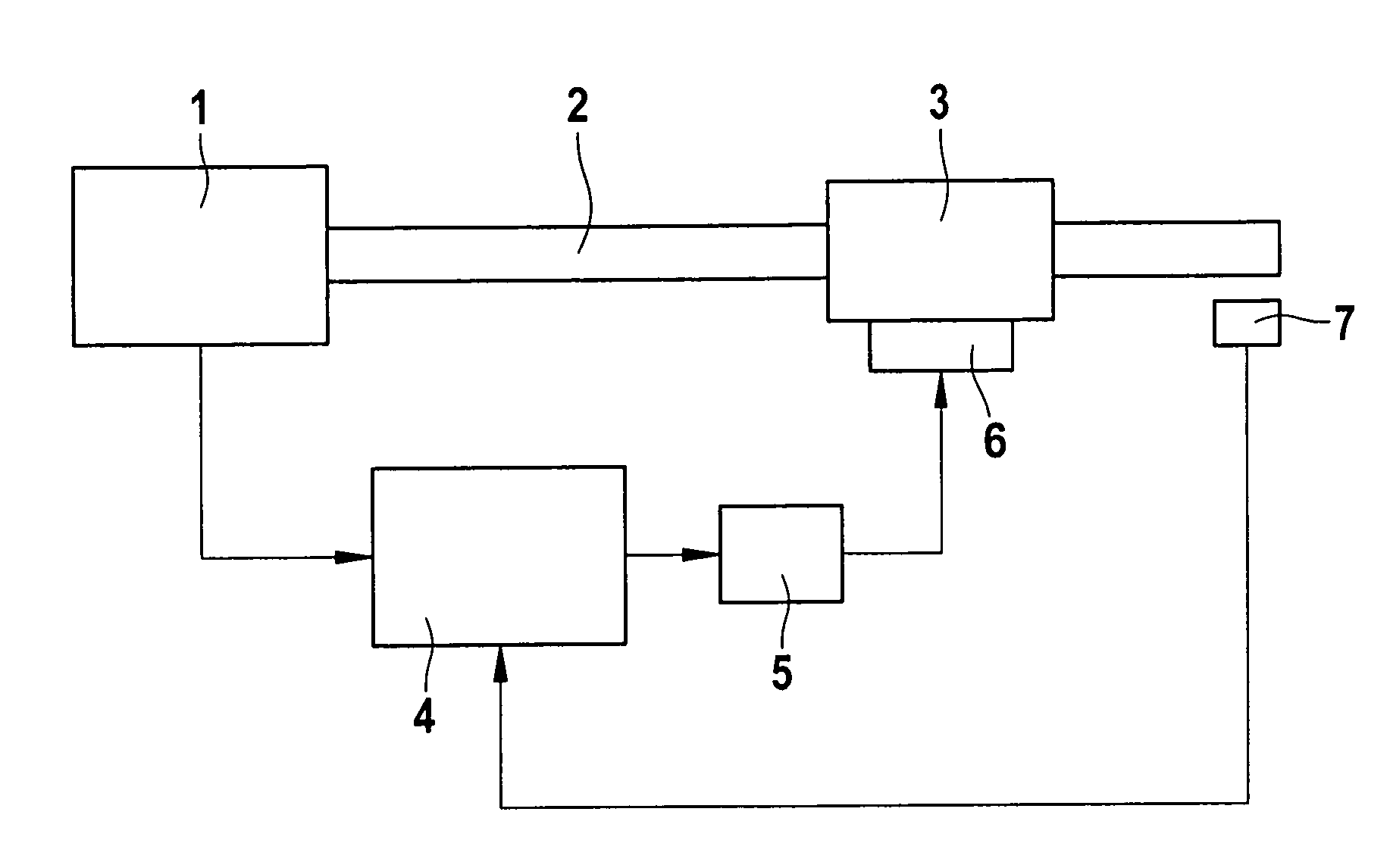
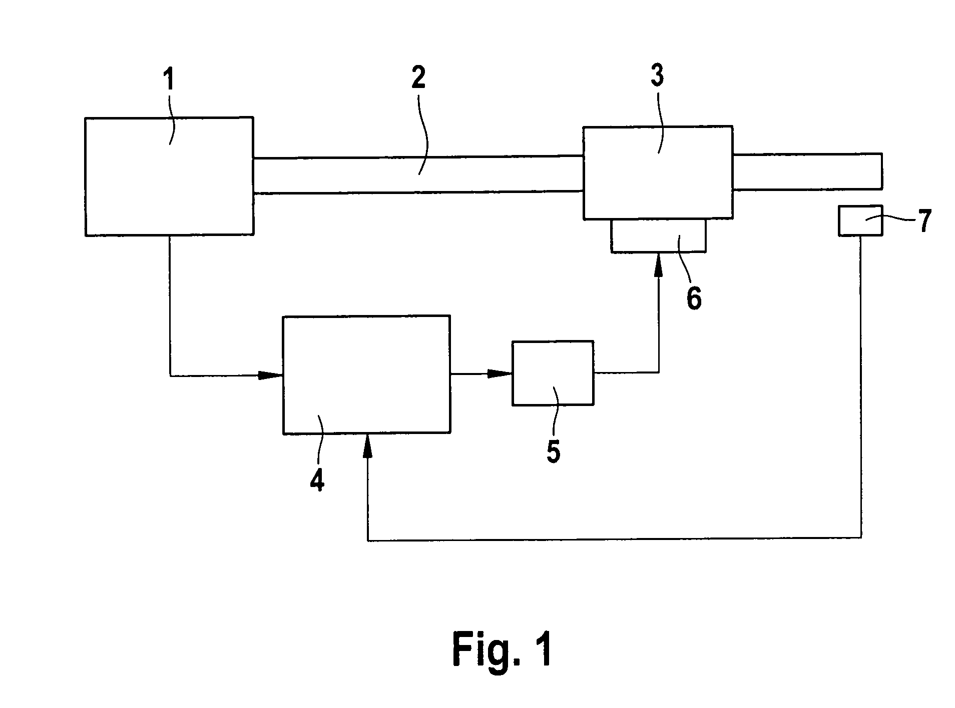
[0017]FIG. 1 shows a sound control device according to the present invention which is provided for controlling the sound which is emitted by a muffler 3. Muffler 3 is connected to an internal combustion engine 1 of a vehicle via a pipe 2. For controlling the sound emitted by muffler 3, a controller 4 is provided, which generates a sound control signal, with which an amplifier 5 is activated which in turn activates a sound converter 6 which is situated on muffler 3 and designed to inject the amplified sound control signal into muffler 3 in such a way that sound emitted by muffler 3 is appropriately controlled. Moreover, controller 4 is connected to a microphone 7 which picks up the sound emitted by muffler 3, in this case the sound at a muzzle pipe of an exhaust system composed of pipe 2 and muffler 3. Furthermore, controller 4 is connected to internal combustion engine 1 or a control device of internal combustion engine 1 in such a way that controller 4 receives information about th...


PUM


Abstract

A method for sound control in a unit of the engine periphery of an internal combustion engine of a vehicle, in particular in an exhaust system of the internal combustion engine, a sound control signal being generated based on a detected sound emission of the unit and injected into the unit, and the sound control signal is also generated as a function of the operating mode of the internal combustion engine.

Description

FIELD OF THE INVENTION[0001]The present invention relates to a method for sound control in a unit of the engine periphery of an internal combustion engine of a vehicle, in particular in an exhaust system of the internal combustion engine, based on a detected sound emission of the unit, a sound control signal being generated and injected into the unit. Furthermore, the present invention relates to a sound control device for executing such a method and a computer program having program code for executing all steps of such a method.BACKGROUND INFORMATION[0002]It is known from the related art to control undesirable sound signals of the exhaust system of a vehicle having an internal combustion engine by actively controlling the noise using a suitable compensating sound field. For this purpose, a sound control signal is generated in a control circuit as a function of a sound signal recorded via a microphone, the sound control signal in turn being injected into the muffler of the exhaust s...

Claims


Application Information

Patent Timeline
Patent Type & Authority Applications(United States)
IPC IPC(8): F02B77/13
CPCF01N1/065G10K11/178G10K2210/3039G10K2210/1282G10K2210/12822G10K2210/121G10K11/17823G10K11/17883
Inventor KASSNER, UWE
Owner ROBERT BOSCH GMBH
Learn More