
High-solids, reactive components spray application systems

a reactive component and spray application technology, applied in the direction of superimposed coating process, liquid transferring device, liquid/solution decomposition chemical coating, etc., can solve the problems of cumbersome change of chemistries of coating or polymeric precursors, large system size and bulk, and cumbersome operation of coating or polymeric precursor chemistries

Inactive Publication Date: 2008-07-24
CITADEL RESTORATION & REPAIR
View PDF24 Cites 23 Cited by
  • Summary
  • Abstract
  • Description
  • Claims
  • Application Information

AI Technical Summary

Benefits of technology

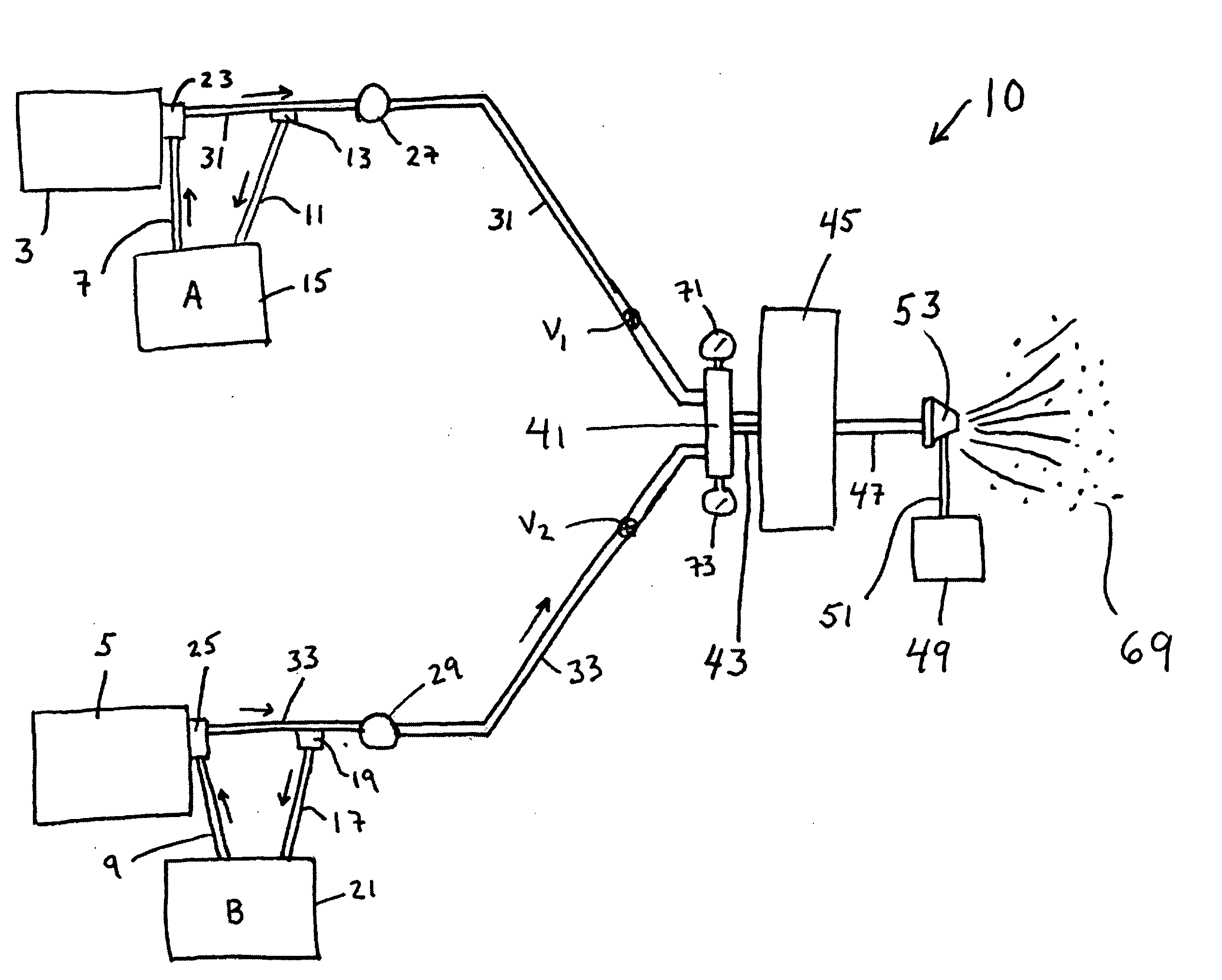
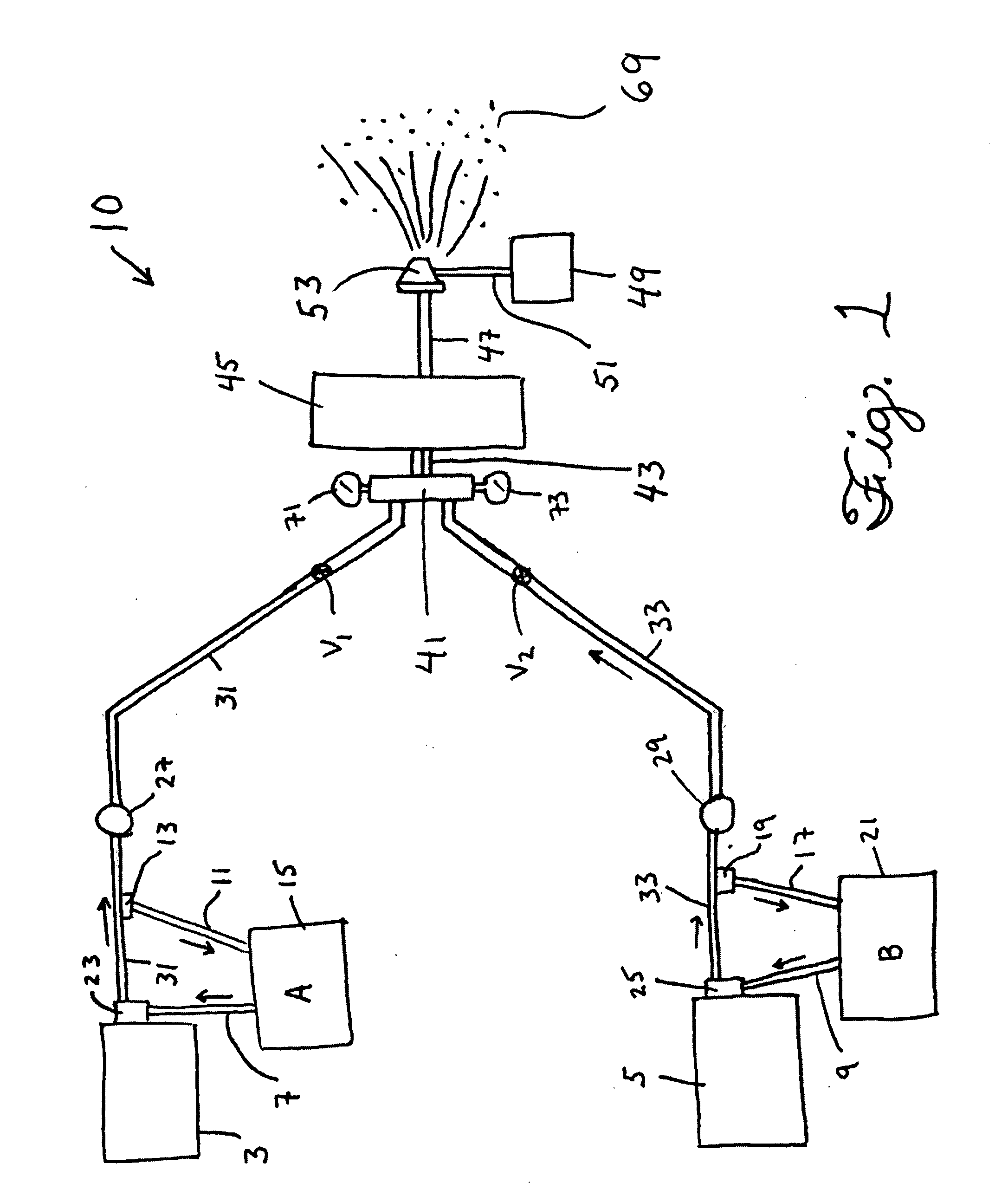
[0007]The present invention provides a system useful for providing coatings to surfaces. A system according to the invention comprises a mixer means having an interior space of any shape or dimension, a first mixer inlet, and a second mixer inlet. The mixer means is adapted to receive two separate chemical feeds and enable their admixture within the interior space. The mixer further comprises a mixer outlet. There is also a first component metering system which includes a first component reservoir having an interior. There is a first peristaltic pump means, comprising a first tube having an inlet end and an outlet end. There is also a first peristaltic pump head sufficiently disposed along the length of said first tube, between its inlet end and said outlet end, so that when the first peristaltic pump head is operational, it causes the fluid present in the interior of that portion of the first tube that is disposed between the first peristaltic pump head and the inlet end of the first tube to exist at a first pressure, and simultaneously causes the fluid present in the interior of the portion of the first tube that is disposed between the first peristaltic pump head and the outlet end of the first tube to exist at a second pressure that is higher than the first pressure. The inlet end of the first tube is in fluid communication with the interior of the first component reservoir, and wherein the outlet end of the first tube is in fluid communication with the first mixer inlet. There is also a second component metering system which includes a second component reservoir having an interior, and a second peristaltic pump means, comprising a second tube having an inlet end and an outlet end. There is a second peristaltic pump head sufficiently disposed along the length of the second tube, between its inlet end and the outlet end, so that when the second peristaltic pump head is operational, it causes the fluid present in the interior of the portion of the second tube that is disposed between the second peristaltic pump head and the inlet end of the second tube to exist at a third pressure, and simultaneously causes the fluid present in the interior of the portion of the second tube that is disposed between the second peristaltic pump head and the outlet end of the second tube to exist at a fourth pressure that is higher than the third pressure. The inlet end of the second tube is in fluid communication with the interior of the second component reservoir, and the outlet end of the second tube is in fluid communication with the second mixer inlet. There is a mixer effluent line, having a first end portion and a second end portion, wherein the first end portion of the mixer effluent line is in fluid communication with the mixer outlet. There is also an atomizing nozzle having a fluid inlet, wherein the fluid inlet of the atomizing nozzle is in fluid communication with the second end portion of the mixer effluent line. The first pressure, may be higher or lower than the third pressure, by any amount of pressure, and the second pressure may be higher or lower than the fourth pressure, by any amount of pressure.

Problems solved by technology

While initial investment for such systems can be on the order of $25,000 and upwards, another disadvantage is that these systems comprise pumps whose internal components and elements come into direct contact with the chemical components used in producing the final coating composition.
Additionally, such systems are typically large and bulky.
These combined features make it cumbersome for an operator to change chemistries of the coating or polymeric precursor being produced by the admixture of an isocyanate with an isocyanate-reactive material, such as a polyamine, polyol, etc.
This difficulty in changing chemistries which results inherently from the nature of the prior art equipment also applies to those cases where the operator desires to change the color of the material being made.
This often entails the use of volatile and expensive solvents, which are not only costly but must also be handled and disposed of in environmentally-compliant ways.
The time investment for such flushings is a source of added cost of applying architectural and other polyurea coatings on an industrial scale.

Method used


Image

  • High-solids, reactive components spray application systems
  • High-solids, reactive components spray application systems

Examples


Embodiment Construction

[0009]Referring to the drawings and initially to FIG. 1 there is shown a block schematic diagram of a system 10 for providing a curable polymeric mixture according to the invention. In this embodiment are shown a first peristaltic pump head 23 and a second peristaltic pump head 25, each of which are driven by a first pump drive 3 and a second pump drive 5, respectively. Peristaltic pumps are known in the art to be a type of positive displacement pump useful for pumping fluids. In one configuration, referred to as rotary peristaltic pumps, the fluid to be pumped is contained within a flexible tube fitted inside a circular pump casing. In the rotary configuration, a roller with a number of “rollers”, “shoes” or “wipers” as they may be called are attached to the external circumference compresses the flexible tube. As the rotor turns, the part of tube under compression closes, thus forcing the fluid to be pumped to move through the tube. Additionally, as the tube opens to its natural st...


PUM

PropertyMeasurementUnit
pressureaaaaaaaaaa
current flowaaaaaaaaaa

Abstract

Provided herein is a system useful for producing polymeric coatings on substrates, by means of a spray that is produced from impinging a compressed gas on a mixture that comprises an organic polyisocyanate and an isocyanate-reactive component. When a coating is produced from two components in accordance with the invention, each component is metered to an atomizing nozzle through peristaltic pumps, which enable increased control over flow characteristics as compared with prior art methods, and which importantly also enables greatly-reduced levels of wasted chemical components and attendant alleviated need for the use of volatile or expensive solvents in equipment cleaning operations. Uncured coating precursor material is allowed greater residence time on the target substrate prior to final cure using a system an process of the invention, which results in coatings having greater integrity over those produced using prior art equipment and methods, as well as reduced overall cost.

Description

TECHNICAL FIELD [0001]This invention relates generally to polymeric coatings. More particularly, it relates to polymeric coatings which are produced by providing a surface with a reactive mixture that is capable of curing and forming a durable coating.BACKGROUND [0002]Coatings for architectural structures have been in widespread use for centuries, with coats of paint applied to wood or stone being exemplary of simple coatings. With the advent of phosgenation of polyamines to produce polyisocyanates in the 1900's, the fields of polyurethane and polyurea chemistry were opened, yielding a wide range of materials which form the basis for many of today's highly-engineered architectural coatings.[0003]Exemplary of one group of such coatings are polyurea coatings, which are often applied to floors, walls, railroad cars, truckbeds, and other surfaces, as is known in the art. Polyureas are known to be produced by the reaction which ensues upon the admixture of one or more polyisocyanates wit...

Claims


Application Information

Patent Timeline
Patent Type & Authority Applications(United States)
IPC IPC(8): B05B7/00
CPCB05B7/32B05B7/2497B05B12/1418B29B7/7404B29B7/7414B29B7/7419
Inventor ILFREY, PATRICK
Owner CITADEL RESTORATION & REPAIR
Learn More