Pivoting package support

a package support and packaging technology, applied in the field of creels, can solve the problems of affecting the nature of the loading task, and the labor intensive operation of the task of loading a creel, so as to improve the efficiency of the manufacturing process and relieve the stress of the musculoskeletal system

Inactive Publication Date: 2008-07-24
AUTOMATED CREEL SYST
View PDF6 Cites 10 Cited by
  • Summary
  • Abstract
  • Description
  • Claims
  • Application Information

AI Technical Summary

Benefits of technology

[0012]In addition to the advantages of relieving musculo-skeletal stresses on the package loader, the automatic creel loading system of the present invention provides efficiencies for the manufacturing process, particularly for the textile industry.

Problems solved by technology

However, despite their widespread use, the task of loading a creel remains an extremely labor intensive operation involving both gross and fine motor skills.
The nature of the loading tasks presents various risks to repetitive motion injuries such as carpal tunnel syndrome, spinal injuries, and other musculo-skeletal maladies.
Because the package supports are arrayed at varying heights and distances from the delivery platform, the typical laborer is subjected to significant risk of musculo-skeletal injuries presented at each step of the yarn package replacement process.
In addition, the subsequent lifting, transport and manipulation of yarn package when grasped in this manner is particularly stressful on the musculo-skeletal tissues of the hand, wrist, and arm.
Due to the dispersion of the package supports within the creel, frequent bending, lifting, and reaching is required to load the package, leading to shoulder, back and other musculo-skeletal stresses.

Method used


Image

  • Pivoting package support
  • Pivoting package support
  • Pivoting package support

Examples


Embodiment Construction

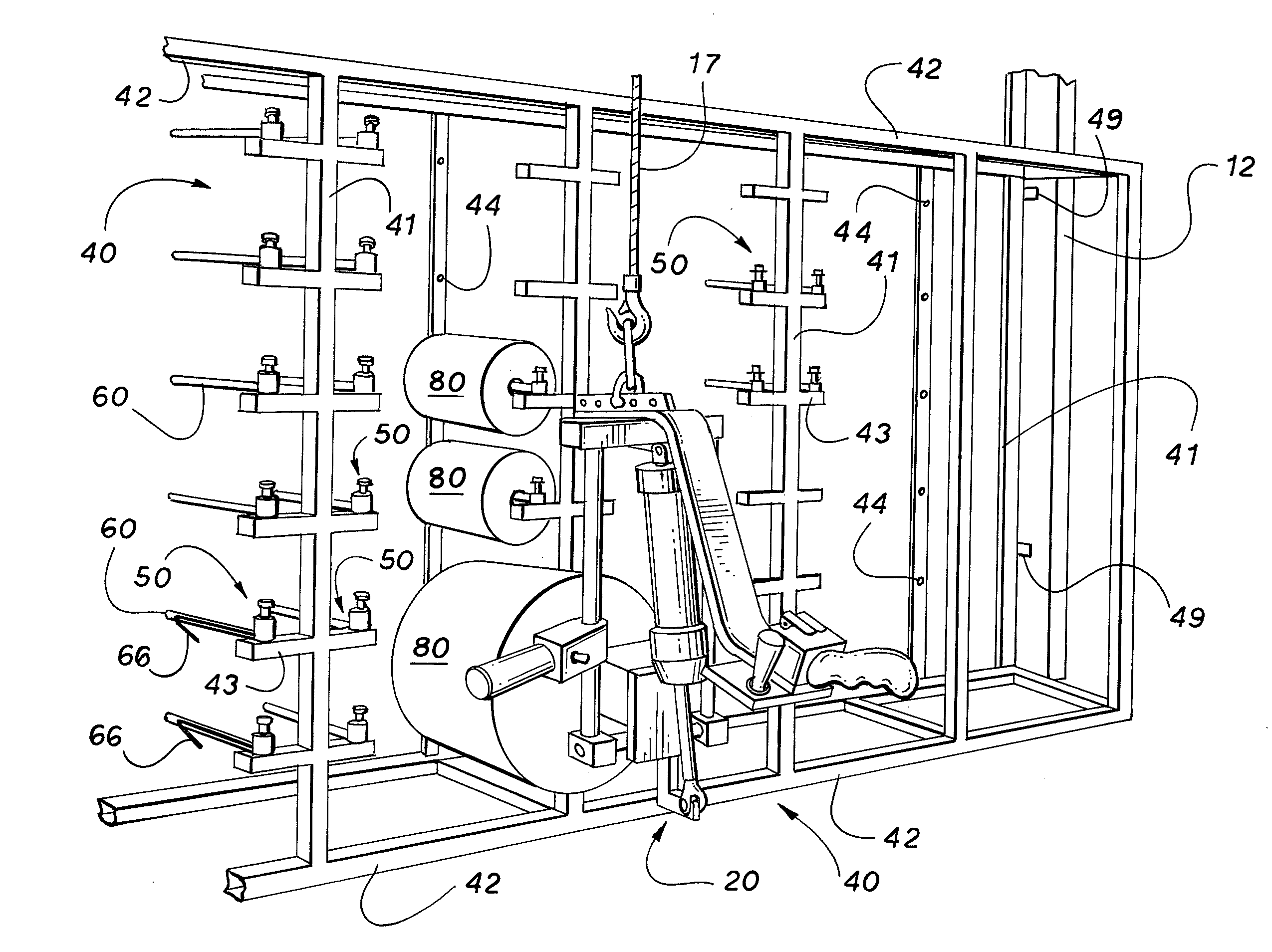
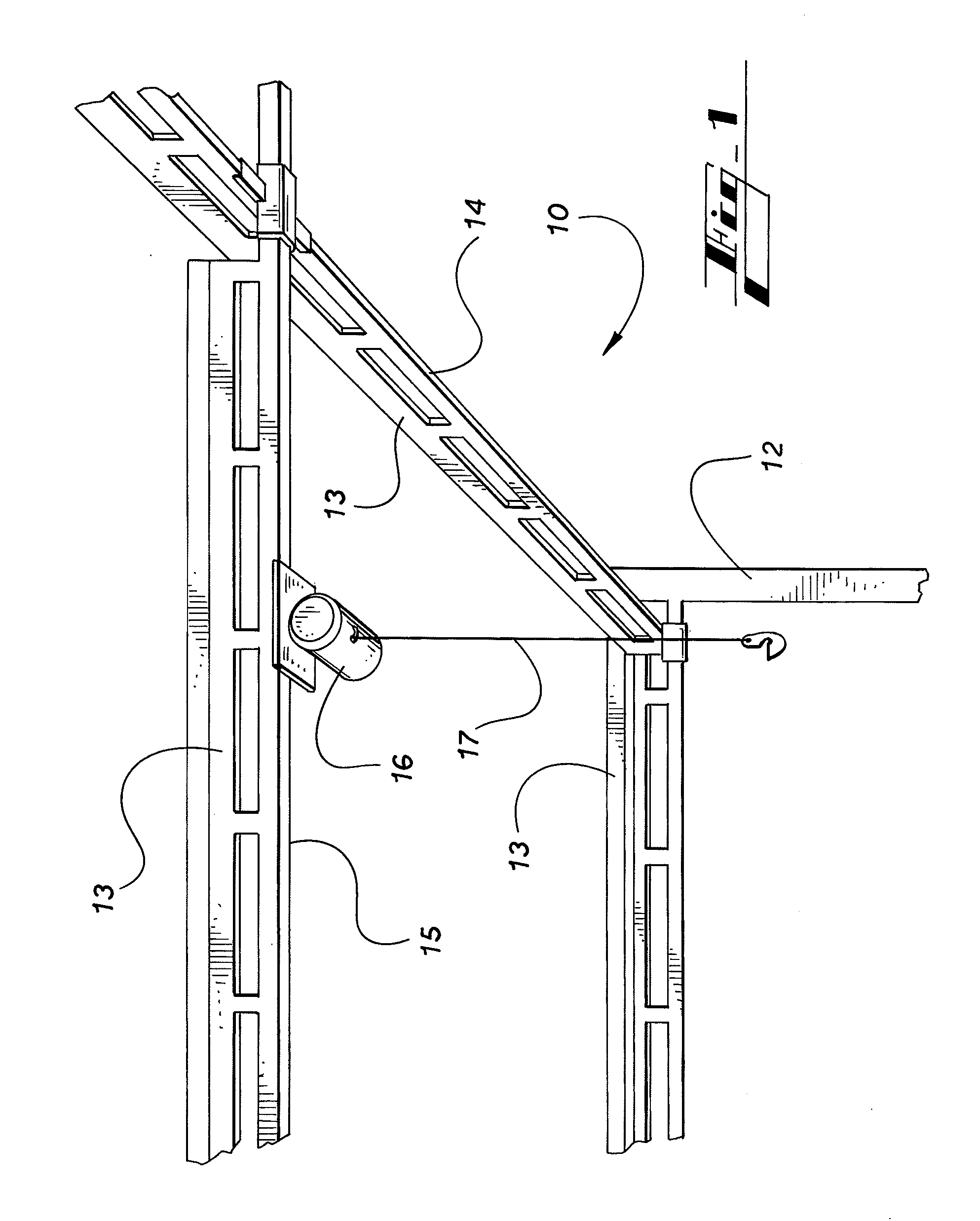
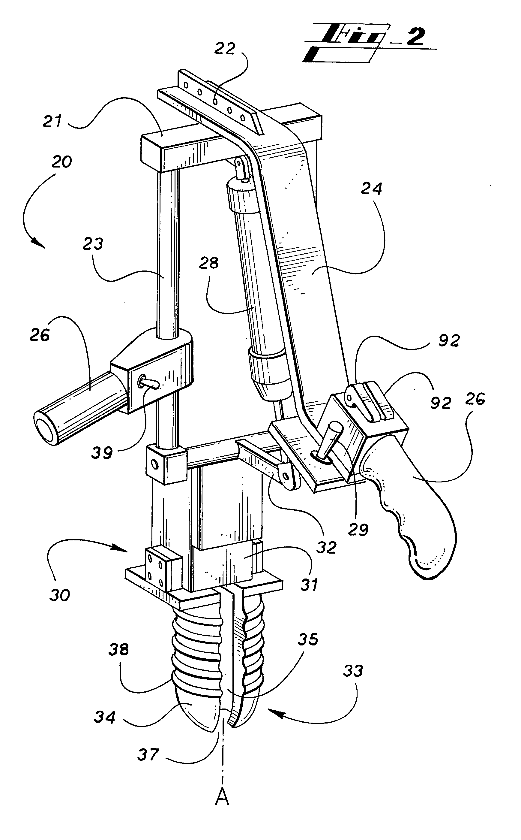
[0024]Referring more particularly to the various drawings FIG. 1 depicts an illustrative automated creel loading system hoist assembly according to the present invention. As seen in FIG. 4, the system generally describes a material loading station, or work station for a manufacturing process, and comprises: a hoist assembly 10; a package manipulator 20 suspended on the hoist assembly 10; and a creel 40, supporting a plurality of packages 80 containing spools of material utilized in the manufacturing process. The workstation may also include a package delivery platform 70 for providing a supply of packages 80 to feed the manufacturing process. Inasmuch as the various aspects of the present invention are directed to supplying and replenishing a supply of stranded material to a manufacturing process requiring the same, the details of the manufacturing process are not particularly germane to the present disclosure, thus embodiments of the invention are applicable outside the textile ind...


PUM


Abstract

A yarn package support for a creel has a support arm that is pivotal about a vertical axis between a loading position and a use position. In the loading position, the package support arm is positioned to load a spool of stranded material, such as yarn or thread. In the use position, the spool and support arm are positioned so that the yarn may be feed into a weaving apparatus. The pivot arrangement permits a laborer to reposition the support arm in a single handed action.

Description

CROSS-REFERENCE TO RELATED APPLICATIONS[0001]This application claims the benefit of prior U.S. Provisional application Ser. No. 60 / 885,743, filed Jan. 19, 2007.FIELD OF THE INVENTION[0002]The present invention generally relates to creels used for supporting a plurality of packages or spools of stranded materials and automated loading of such spools on the creel. More particularly, the present invention relates to an automated creel loading system for use in the textile industry, wherein the stranded materials are yarns or other textile products. With even greater particularity, the invention relates to an automated handling apparatus and method for transferring a yarn package from a pallet or other material delivery platform to any one of a plurality of package support holders located on the creel. The invention further contemplates an improved package support holder for the creel.BACKGROUND OF THE INVENTION[0003]The use of creels for supporting a plurality of yarn packages is well ...

Claims


Application Information

Patent Timeline
Patent Type & Authority Applications(United States)
IPC IPC(8): B65H75/18
CPCB65H49/16B65H2701/31B65H2402/414B65H67/065
Inventor CHADWICK, DAVID
Owner AUTOMATED CREEL SYST
Why Eureka
Try Eureka