Method and System for Equalizing Cable Losses in a Distributed Antenna System

Active Publication Date: 2008-07-24
CORNING OPTICAL COMM WIRELESS
View PDF37 Cites 49 Cited by
  • Summary
  • Abstract
  • Description
  • Claims
  • Application Information

AI Technical Summary

Benefits of technology

[0020]In addition, wireless services (e.g. Wi-Fi) are being introduced in increasingly higher frequency bands (e.g. WLAN at 2.4 GHz and especially 5.5 GHz). This creates challenges when using passive antennae because analog signals are attenuated as they propagate along the coax cable and the magnitude of attenuation depends on the characteristics of the cable, and is generally proportional to the length of the cable and to the frequency of the signal. For in-building DAS deployments, cable lengths can reach 300′ or more, and the attenuation experienced by high frequency signals along such a length of cable will significantly degrade the downlink power of the signal as it reaches the antenna (the uplink signal would be subject to a similar problem). The result is a substantially reduced coverage radius for that frequency band around the antenna and the associated increased cost to add more antennae.
[0021]Introducing amplification in the antenna can compensate for the losses in the cable, for both the uplink and downlink signals, and thus alleviate the problem. For example, some single-service DAS platforms use single-band (a.k.a. narrowband) antennae which are active, in other words have integrated amplifiers for the specific band being addressed. Further, a multi-service DAS which requir

Problems solved by technology

This is because passive antennae are cheaper and more reliable than powered antennae and the introduction of power amplifiers in the antenna can introduce interference between bands that requires the use of bulky and expensive filters to mitigate.
A common problem of virtually any DAS installation is that the cables connecting the different antennae to the wiring closet are not of equal lengths.
One of the problems created by the disparity in antenna cable lengths is the varying coverage radius.
This variance can complicate the antenna location planning process and would typically increase the cost of the project.
For signals using the non-aggregated configuration, where each antenna is radiating a different signal, the variation in coverage radius can complicate (automatic) frequency channel assignment processes and may introduce interference.
Another problem created by the disparity in antenna cable lengths is narrowing of system uplink dynamic range in systems in aggregated configurations.
A more restricted dynamic range can impact the design and deployment as well as the cost of the DAS.
This in turn has a negative financial impact as more antennas may be required for a given coverage area.
The disparity in antenna cable run length further exacerbates the problem, since the system design now needs to take into account the case where the weakest signal is received through an antenna with a long cable run while the strong signal is received through an antenna with a short cable run.
The end result would be a further decrease in antenna

Method used


Image

  • Method and System for Equalizing Cable Losses in a Distributed Antenna System
  • Method and System for Equalizing Cable Losses in a Distributed Antenna System
  • Method and System for Equalizing Cable Losses in a Distributed Antenna System

Examples


Embodiment Construction

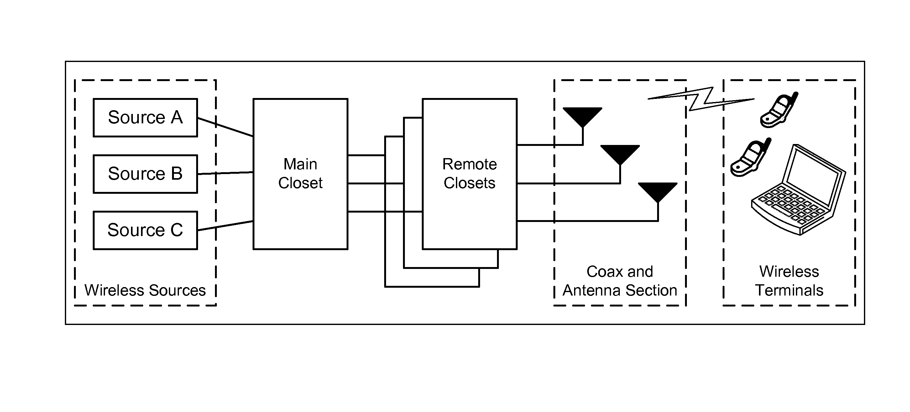
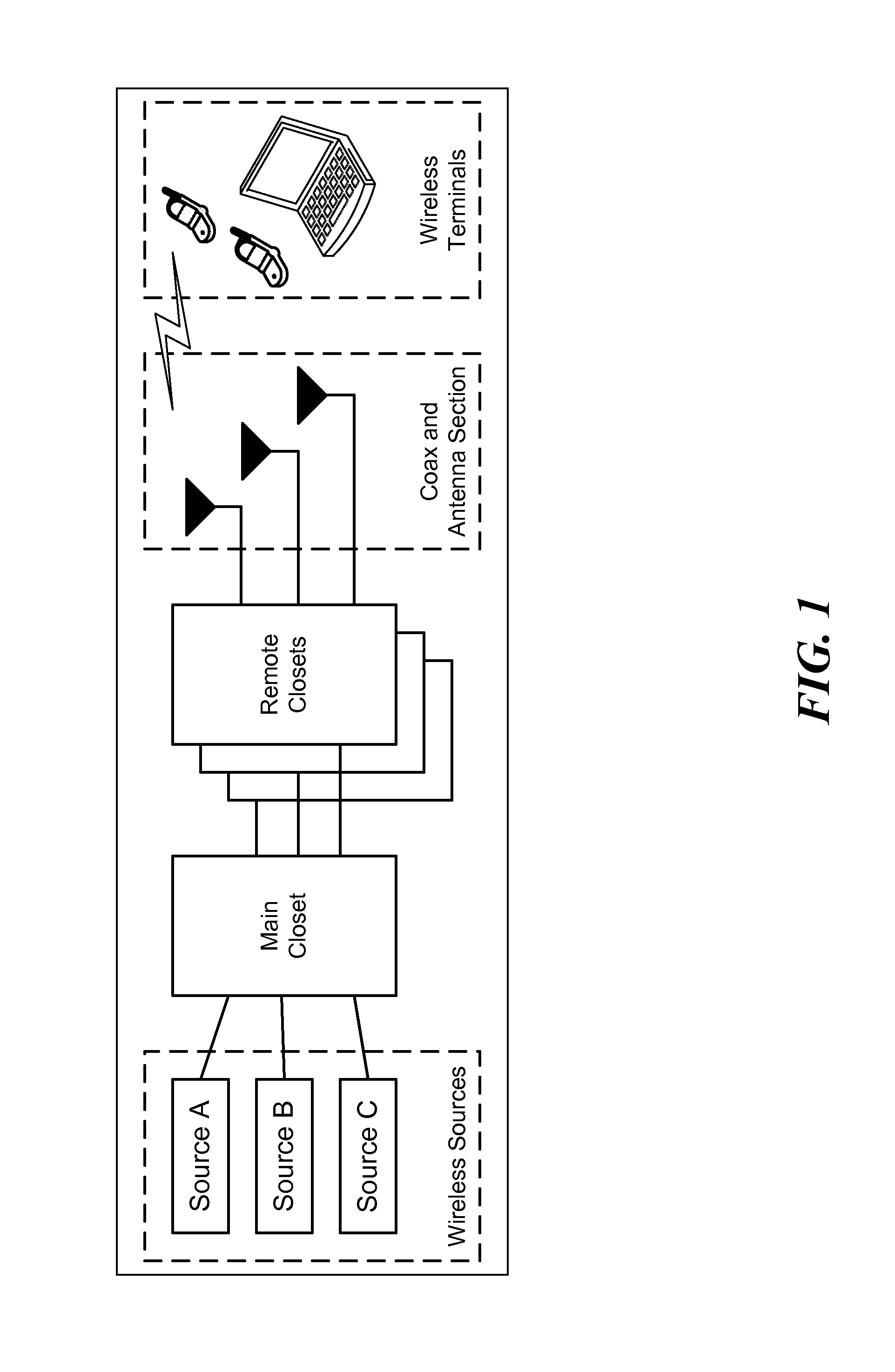
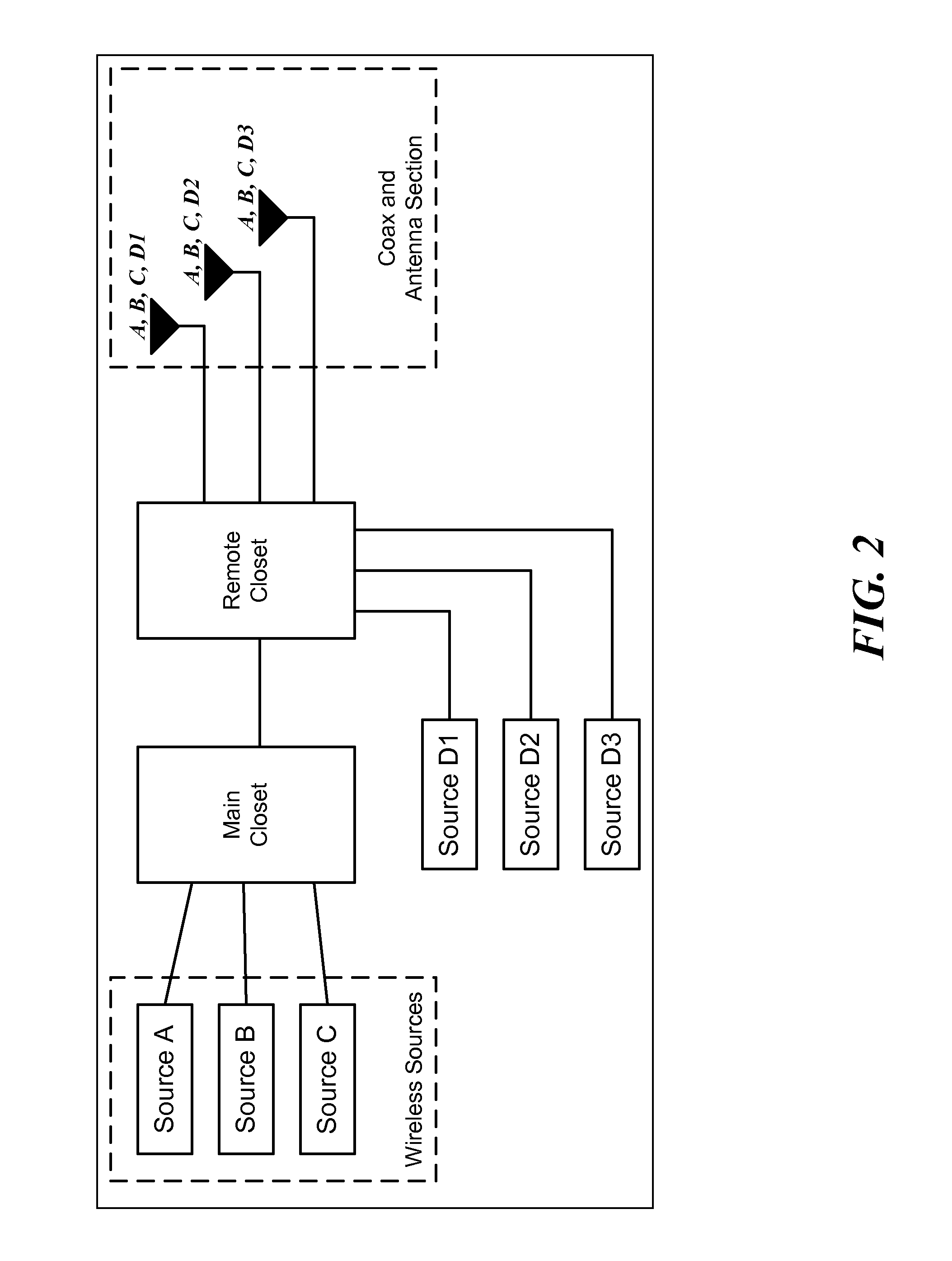
[0042]The present invention is directed to a method and system for compensating for cable losses in distributed antenna systems. In accordance with one embodiment of the invention, the system includes a measurement component adapted to receive a measurement signal having a known frequency and power level and for determining or estimating the losses of a signal transmitted at one end of the cable run and received at the other end of the cable run. In accordance with the invention, the system further includes an equalization component adapted for receiving the information about the determined or estimated cable run losses and for adjusting the signal level to a predetermined value. Each cable run in the DAS can include the system according to the invention whereby the signal levels of each cable run can be adjusted to the predetermined value. In one embodiment, the signal level corresponding a particular service or frequency range or band at the connection to the antenna unit can adju...


PUM


Abstract

The invention is directed to a method and system for equalizing the signal losses over cable runs in a Distributed Antenna System (DAS). In a DAS, two or more antennae are connected to the system by cable runs that can vary widely in length. As a result, the signal loss over a given cable run can also vary widely which can impact the design and deployment of the DAS and reduce antenna spacing. In addition, for a broadband DAS that supports many frequency bands or ranges using a common antenna unit, the signal losses vary with respect to frequency further making it difficult to equalize the cable losses. According to one embodiment of the invention, the method and system provide for measuring and adjusting the signal losses of each cable run to be a predefined value. According to another embodiment of the invention, the DAS can include a hybrid passive-active antenna unit which includes a frequency multiplexer that separates the signal into frequency bands or ranges that are connected to an antenna element associated with a particular frequency band or range. Where a single frequency band needs to be amplified (or attenuated), a single band amplification block (SBAB) can be inserted in the connection between the frequency multiplexer and the antenna element to amplify (or attenuate) the desired frequency band. Where more than one frequency band need to be amplified (or attenuated), a multiband amplification block (MBAB) can be inserted in the connection between the frequency multiplexer and the appropriate antenna element to amplify (or attenuate) the desired frequency bands.

Description

CROSS-REFERENCE TO RELATED APPLICATIONS[0001]This application claims any and all benefits as provided by law of U.S. Provisional Application No. 60 / 885,470 filed Jan. 18, 2007, which are hereby incorporated by reference in their entirety.STATEMENT REGARDING FEDERALLY SPONSORED RESEARCH[0002]Not ApplicableREFERENCE TO MICROFICHE APPENDIX[0003]Not ApplicableBACKGROUND[0004]1. Technical Field of the Invention[0005]The present invention is directed to Distributed Antenna Systems and more particularly, to methods and systems for compensating for signal loss or attenuation in order to provide predictable signal strength at the uplink and downlink endpoints.[0006]Distributed Antenna Systems (“DAS”) are used to provide or enhance coverage for wireless services such as Cellular Telephony, Wireless LAN and Medical Telemetry inside buildings and over campuses. The general architecture of a DAS is depicted in FIG. 1.[0007]A single DAS can serve a single wireless service or a combination of wire...

Claims


Application Information

Patent Timeline
IPC IPC(8): H01Q21/00G01R29/08
CPCH04B1/0064H04B7/06H04B17/21H04W88/085H04B17/12H04B7/08
Inventor OREN, YAIRBERLIN, IGORSABAN, OFER
Owner CORNING OPTICAL COMM WIRELESS
Why Eureka
Try Eureka