Control circuit having an impedance modulation controlling power converter for saving power

a control circuit and power converter technology, applied in the direction of electric variable regulation, process and machine control, instruments, etc., can solve the problems of power loss such as conduction loss and switching loss, significant loss of switching at light load, and drawback of prior arts detection circuit of load, so as to save power and increase resistance of resistive device. , the effect of saving power

Active Publication Date: 2008-07-24
SEMICON COMPONENTS IND LLC
View PDF14 Cites 19 Cited by
  • Summary
  • Abstract
  • Description
  • Claims
  • Application Information

AI Technical Summary

Benefits of technology

[0005]The present invention provides a control circuit including a standby circuit and a switching control circuit. The standby circuit is used to detect the load condition and on / off states of the power converter for saving power. The standby circuit includes a feedback input circuit and a comparison circuit. The feedback input circuit is coupled to the output of the power converter through the feedback loop of the power converter. The comparison circuit is coupled to the feedback input circuit to generate a mode signal when a feedback signal in the feedback input circuit is lower than a threshold signal. A resistive device and an external capacitor are coupled to the feedback signal. The resistance of the resistive device is increased in response to the enablement of the mode signal. Therefore, the impedance of the feedback input circuit is changed in response to the change of the mode signal. The mode signal is further coupled to turn off the switching control circuit of the power converter for saving power. The capacitance of the external capacitor associated with the resistance of the resistive device determines the off period of the switching control circuit of the power converter.

Problems solved by technology

However, the switching of power converter causes power losses such as conduction loss and switching loss.
The switching loss is the significant loss at light load.
However, the drawback of these prior arts is the detection circuit of the load.
The switching frequency of the power converter cannot be programmed especially when acoustic noise is generated.
Besides, the output ripple caused by the burst switching is uncontrollable.

Method used


Image

  • Control circuit having an impedance modulation controlling power converter for saving power
  • Control circuit having an impedance modulation controlling power converter for saving power
  • Control circuit having an impedance modulation controlling power converter for saving power

Examples


Embodiment Construction

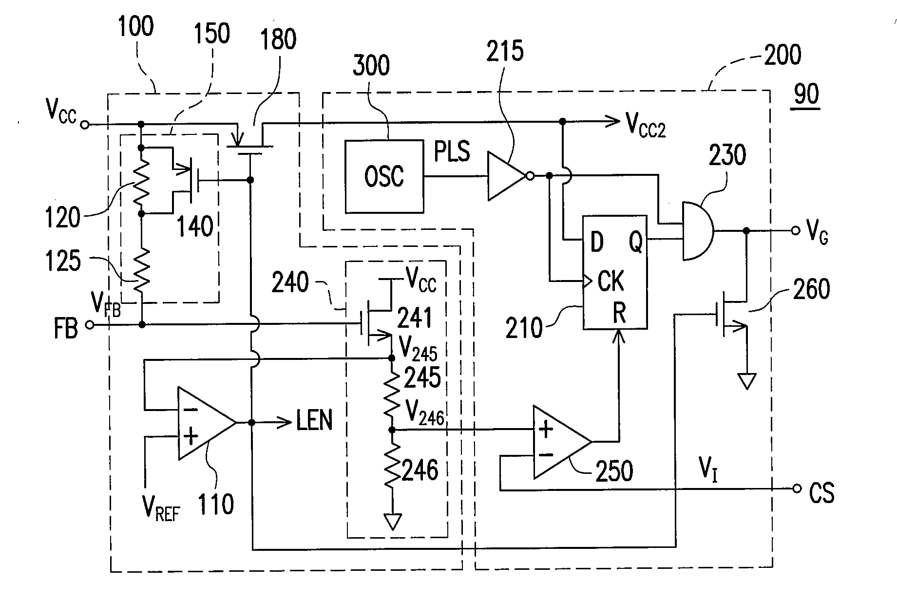
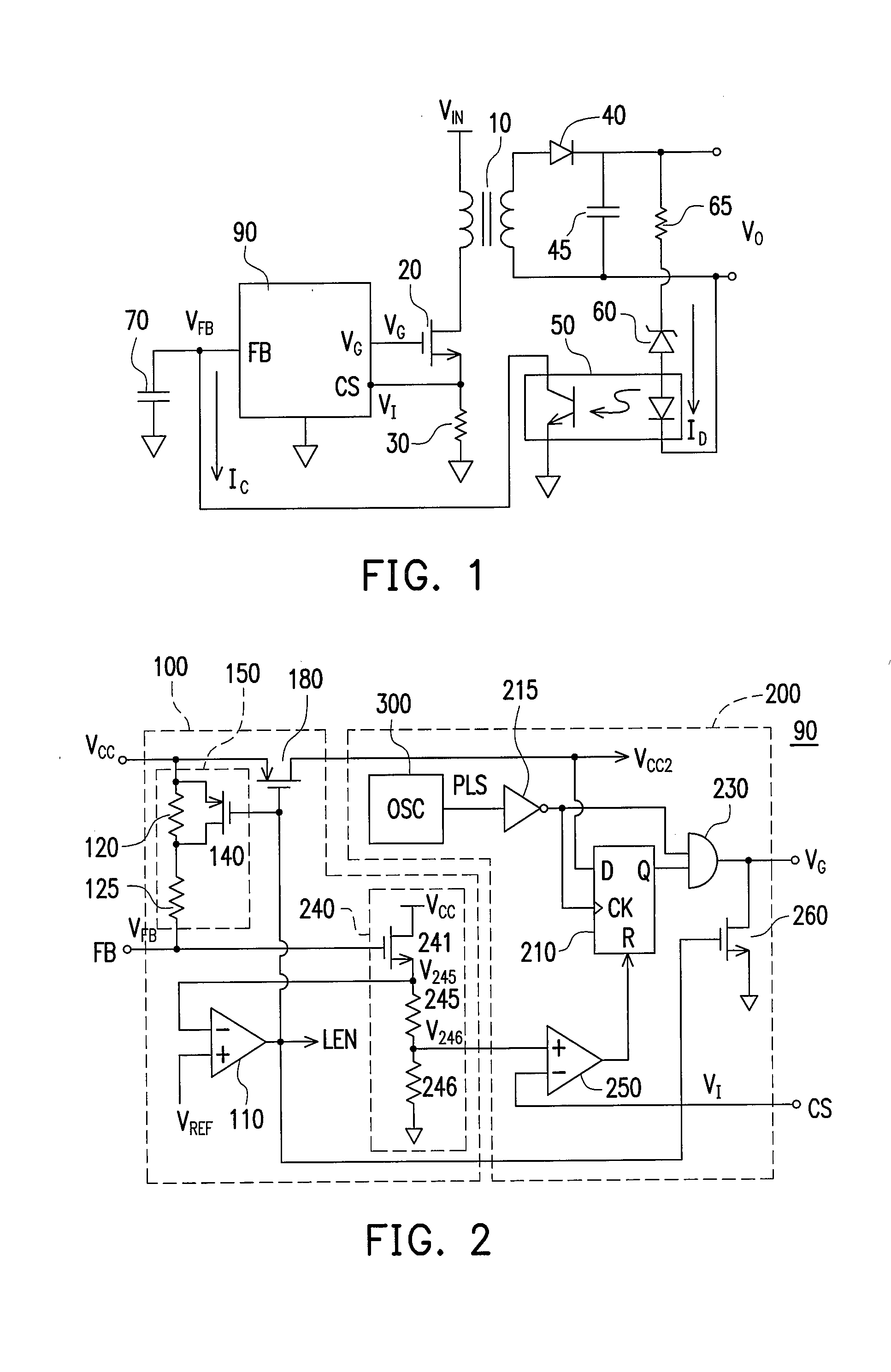
[0011]FIG. 1 shows a circuit schematic of a power converter. A control circuit 90 generates a switching signal VG to regulate the output of the power converter in response to a feedback signal VFB at a feedback terminal FB. The switching signal VG drives a power transistor 20 for switching a transformer 10. The transformer 10 is connected to an input voltage VIN of the power converter for energy store and power transfer. The energy of the transformer 10 is transferred to the output VO of the power converter through a rectifier 40 and a capacitor 45. A resistor 30 is connected serially with the power transistor 20 to generate a current signal VI at the current sense terminal CS in response to the switching current of the transformer 10. Through a resistor 65, a zener diode 60 is coupled from the output voltage VO to an opto-coupler 50. The output of the opto-coupler 50 is coupled to the feedback terminal FB of the controller 90 to form a feedback loop. The pulse width of the switchin...


PUM


Abstract

A standby circuit is provides to on / off a power converter for power saving. The standby circuit includes a comparison circuit. The comparison circuit is coupled to a feedback loop of the power converter to generate a mode signal when a feedback signal of the feedback loop is lower than a threshold signal. A resistive device is coupled to the feedback loop. The resistance of the resistive device is increased in response to the mode signal. The mode signal is further coupled to turn off a switching control circuit of the power converter.

Description

BACKGROUND OF THE INVENTION[0001]1. Field of the Invention[0002]The present invention relates to power converters, and more specifically relates to the control of switching power converters.[0003]2. Description of Related Art[0004]Switching power converters have been widely used to provide regulated voltage and current. However, the switching of power converter causes power losses such as conduction loss and switching loss. The switching loss is the significant loss at light load. In order to maintain high efficiency of power converter, many techniques have been developed to reduce the power consumption, such as “Full load to no-load control for a voltage fed resonant inverter” by Park, et al, U.S. Pat. No. 4,541,041; “Strobed DC-DC converter with current regulation” by Pace, et al, U.S. Pat. No. 5,028,861; “Control circuit and method for maintaining high efficiency over broad current ranges in a switching regulator circuit” by Wilcox, et al, U.S. Pat. No. 5,481,178; “Switching regu...

Claims


Application Information

Patent Timeline
Patent Type & Authority Applications(United States)
IPC IPC(8): H02M1/08
CPCH02M3/33507Y02B70/16H02M2001/0032H02M3/33523H02M1/0032Y02B70/10
Inventor YANG, TA-YUNG
Owner SEMICON COMPONENTS IND LLC
Why Eureka
Try Eureka