
Two-Channel Multimode Rotary Joint

a rotary joint, multi-mode technology, applied in the direction of optics, instruments, optical light guides, etc., can solve the problems of high cost of elaborate mechanical arrangement, device cannot be constructed to have rotational symmetry, and optical joints of this kind of no interest for many applications, etc., to achieve low transmission loss

Active Publication Date: 2008-07-24
SCHLEIFRING & APPBAU
View PDF99 Cites 21 Cited by
  • Summary
  • Abstract
  • Description
  • Claims
  • Application Information

AI Technical Summary

Benefits of technology

[0010]The invention is based on the object of redesigning a rotary joint for bidirectional transmission of optical signals so that it will have a relatively low transmission loss which is substantially not dependent upon a rotation angle.

Problems solved by technology

However, the high costs of the elaborate mechanical arrangement render an optical joint of this kind of no interest for many applications.
Furthermore, this device cannot be constructed to have rotational symmetry, because at least two light guides must be inserted into the beam path radially from the outside.
A disadvantage of this arrangement is that the attenuation is very large with single-mode fibers.

Method used


Image

  • Two-Channel Multimode Rotary Joint
  • Two-Channel Multimode Rotary Joint

Examples


Embodiment Construction

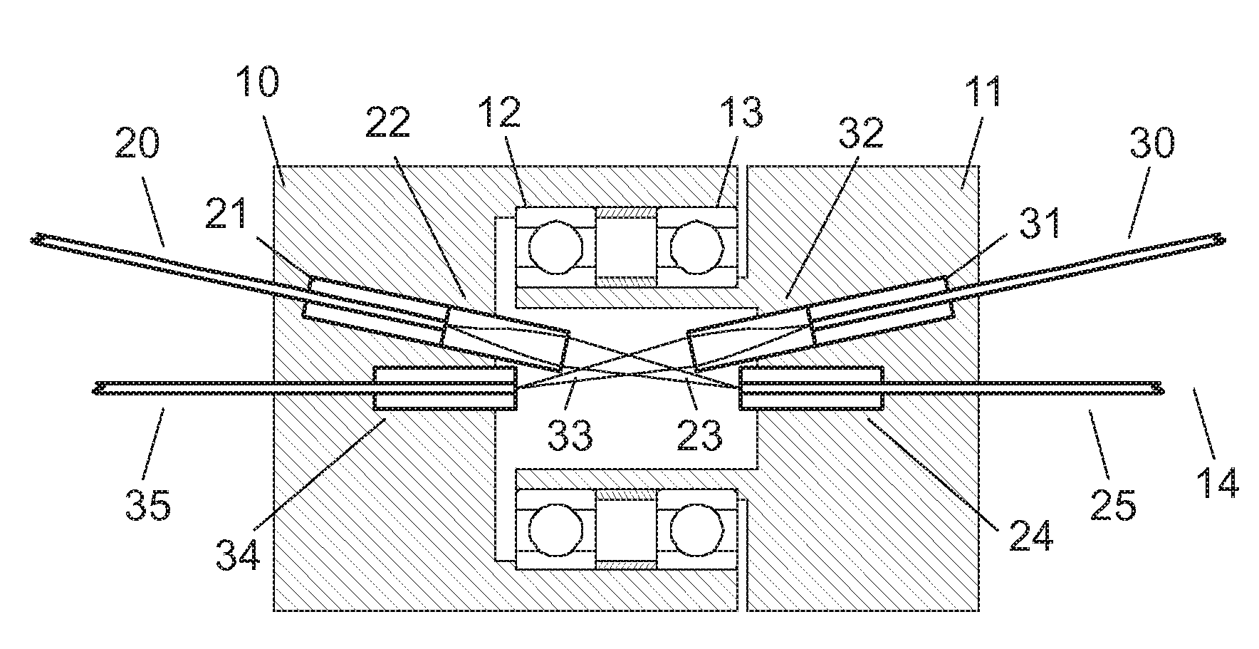
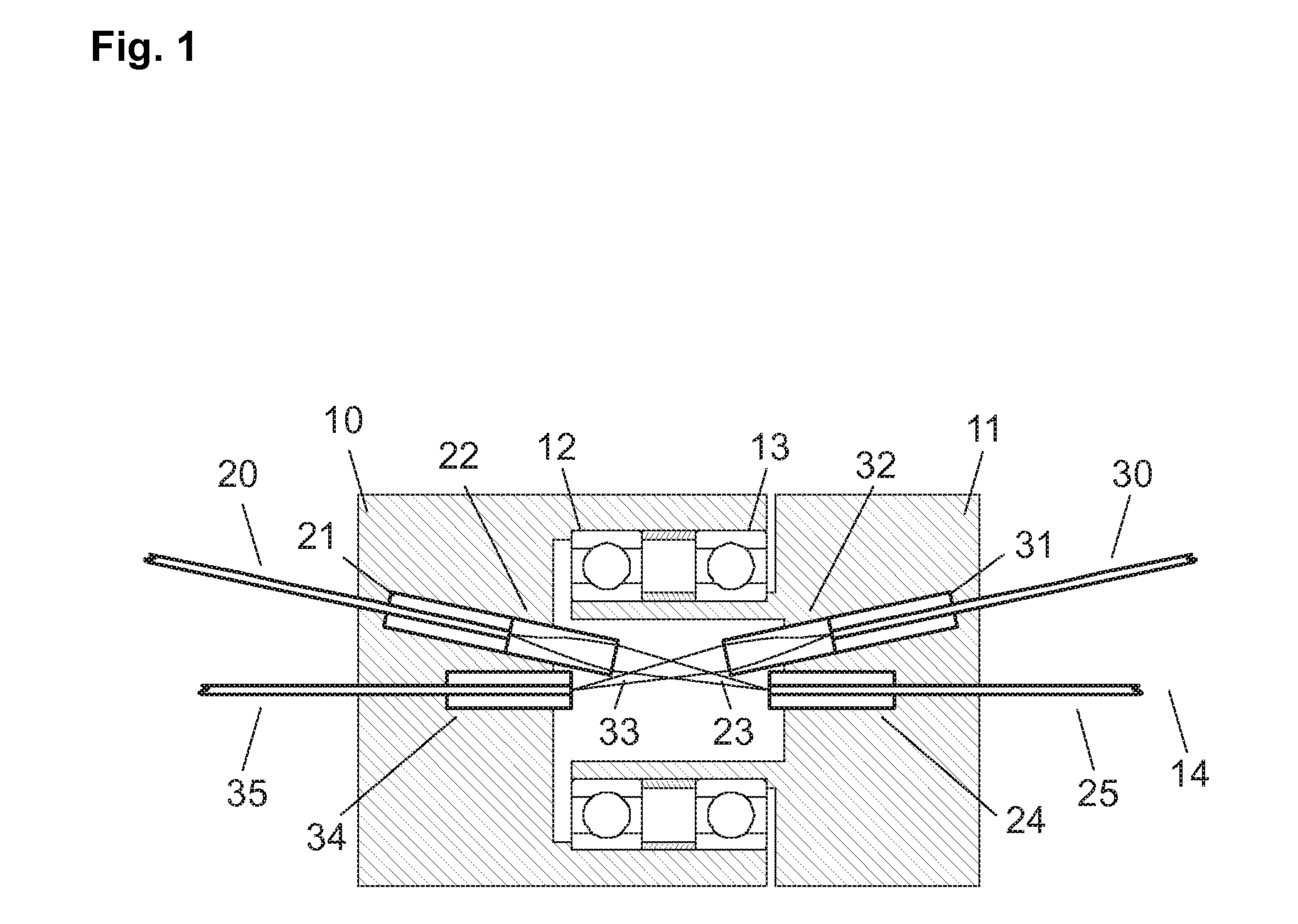
[0014]The device according to the invention comprises a first housing part 10 and also a second housing part 11 which are connected together to be rotatable about the rotation axis 14 by means of a bearing unit 12, 13. The first optical path comprises a first light-waveguide 20 on the first housing part 10 for supplying light, which is accommodated in the first ferrule 21. At the end of the light-waveguide there is provided a first focuser 22 for focusing the light 23 emitted by the light-waveguide onto the second light-waveguide 25. The light-waveguide 25 on the second housing part 11 is itself accommodated in a ferrule 24. The second light path extending in the opposite direction comprises a third light-waveguide 30 on the second housing part 11 for supplying light, the third light-waveguide being accommodated in the ferrule 31. At the end of the third light-waveguide there is provided a second focuser 32 for focusing the light 33 emitted by the light-waveguide onto the fourth lig...


PUM


Abstract

An optical two-channel rotary joint that is also suitable for coupling of single-mode fibers comprises two housing parts that are rotatable relative to each other. Each of these housing parts accommodates a light-waveguide for supplying light and a light-waveguide for withdrawing light. The arrangement has two optical paths adapted to operate in opposite directions, with each light-waveguide for supplying light being coupled with a light-waveguide for withdrawing light. Furthermore, one focuser is disposed on each of the light-waveguides for supplying light, which focuses the light of the light-waveguide for supplying light onto the corresponding light-waveguide for withdrawing light.

Description

PRIORITY CLAIM[0001]The present application claims priority to pending German Application No. 102007004514.1 filed on Jan. 24, 2007.BACKGROUND OF THE INVENTION[0002]1. Field of the Invention[0003]The invention relates to a single-mode rotary joint for optical signals, having two channels, with which the signals can be simultaneously transmitted in opposite directions.[0004]2. Description of the Prior Art[0005]Because of their greater flexibility and robustness, optical bus systems are frequently used instead of cable-bound bus systems. With bus systems of this kind, signals or information are regularly transmitted in two opposite directions of the bus system, in order to make possible a bidirectional communication between different subscribers.[0006]Optical rotary joints are known for transmission of optical signals between units that are rotatable relative to each other.[0007]An optical rotary joint for a plurality of channels, having a Dove prism, is disclosed in U.S. Pat. No. 5,5...

Claims


Application Information

Patent Timeline
Patent Type & Authority Applications(United States)
IPC IPC(8): G02B6/26
CPCG02B6/3604
Inventor POPP, GREGORSEEGER, ANDREAS PHILIPP
Owner SCHLEIFRING & APPBAU
Learn More