Making method for product information

a technology of product information and making method, which is applied in the field of marking product information, can solve problems such as productivity reduction, and achieve the effect of improving productivity and increasing the efficiency of product information marking

Active Publication Date: 2008-07-24
DISCO CORP
View PDF2 Cites 9 Cited by
  • Summary
  • Abstract
  • Description
  • Claims
  • Application Information

AI Technical Summary

Benefits of technology

[0005]It is therefore an object of the present invention to provide a product information marking method which can incre

Problems solved by technology

However, it is troublesome that the product information is marked on each of the

Method used


Image

  • Making method for product information
  • Making method for product information
  • Making method for product information

Examples


Embodiment Construction

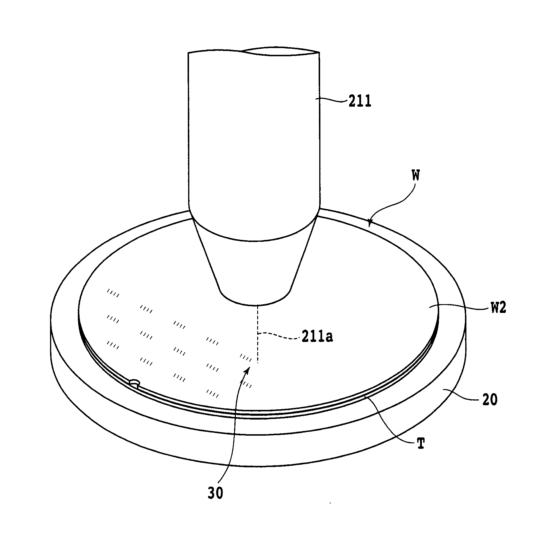
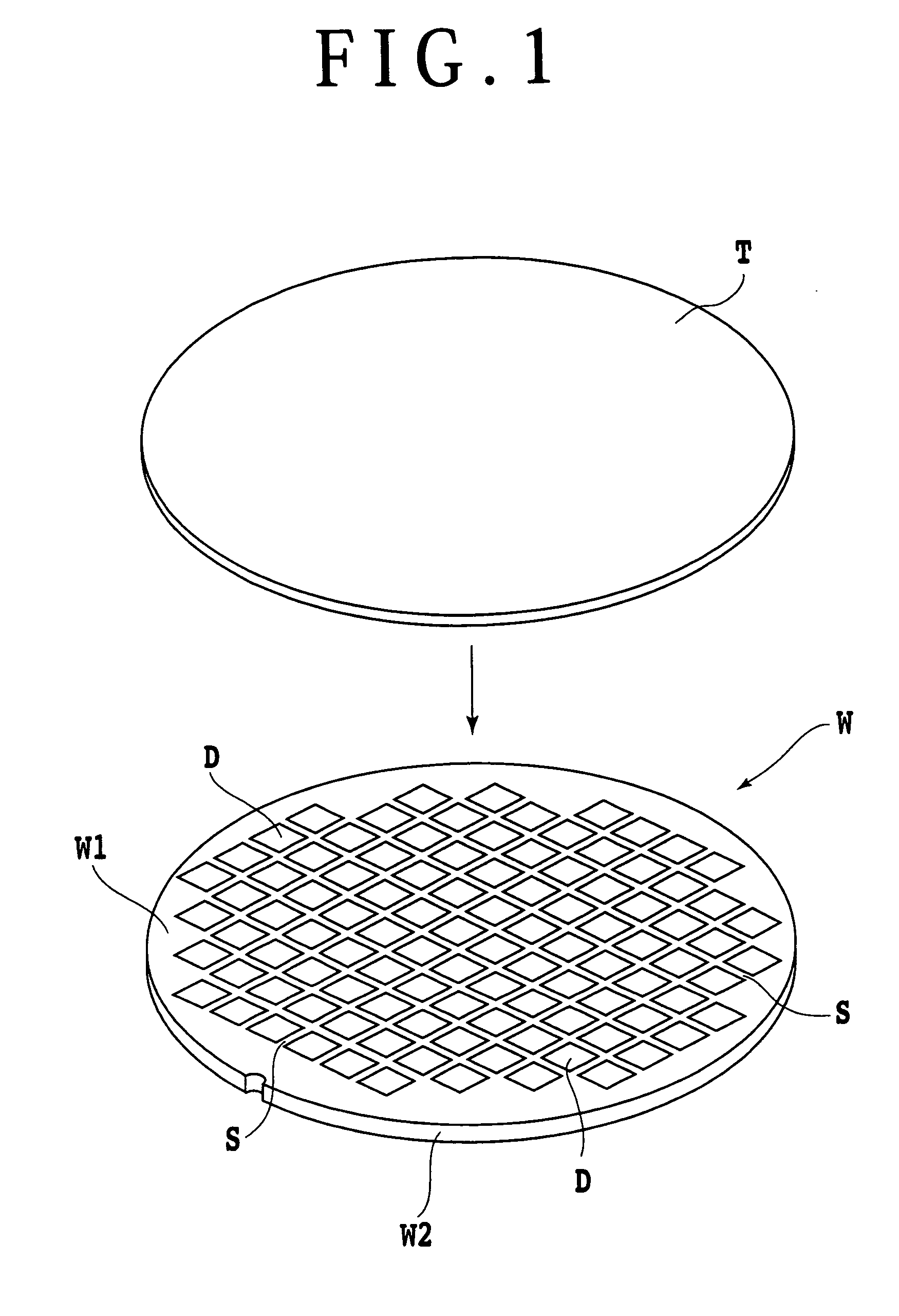
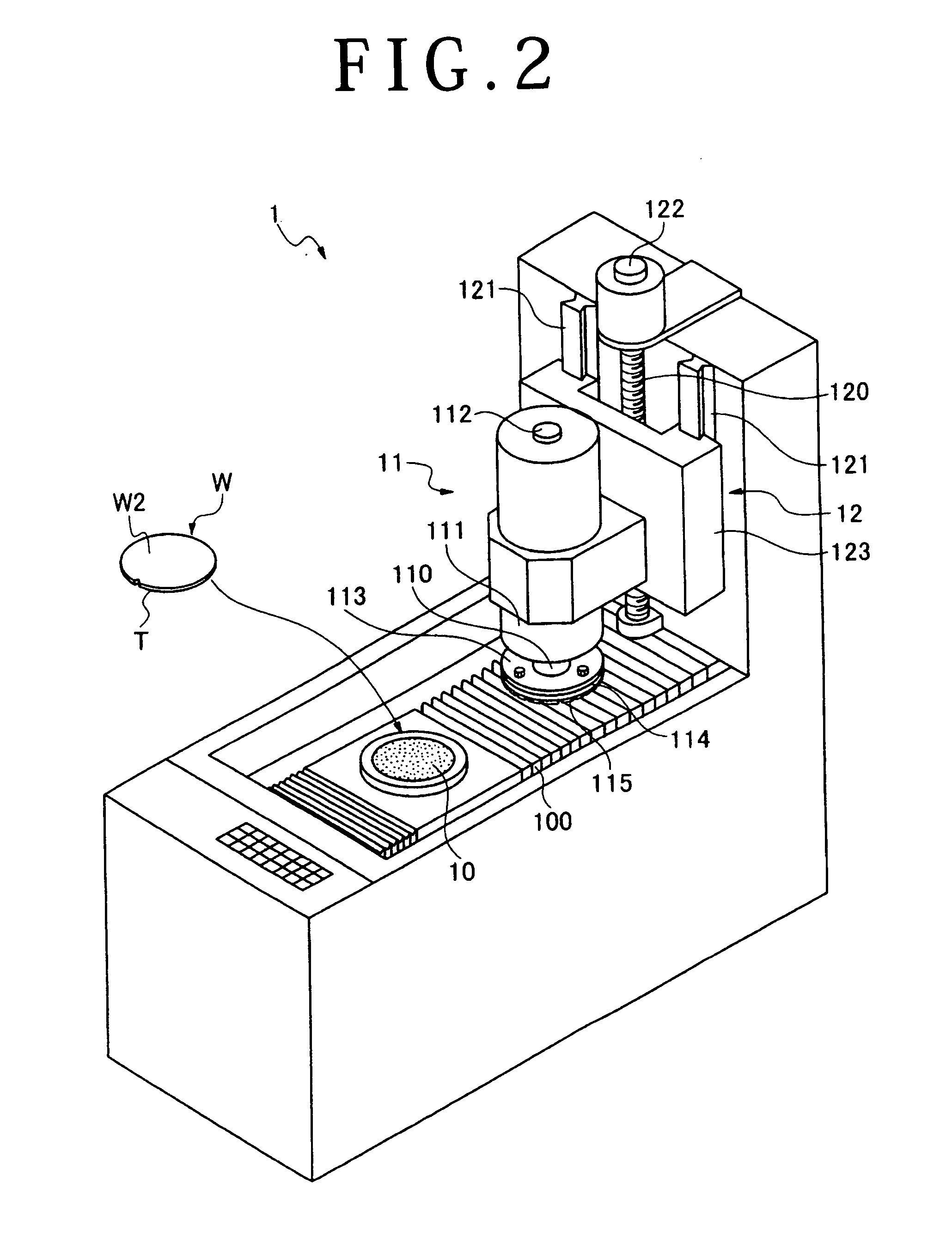
[0017]As shown in FIG. 1, a plurality of devices D are formed on the front side W1 of a wafer W so as to be partitioned by a plurality of separation lines S extending in the vertical and horizontal directions (X and Y directions). A protective tape T is attached to the front side W1 of the wafer W prior to grinding of the back side W2 of the wafer W. In grinding the back side W2 of the wafer W, the wafer W is held on a chuck table 10 of a grinding unit 1 shown in FIG. 2 in the condition where the protective tape T is placed on the under side of the wafer W and the back side W2 of the wafer W is exposed.

[0018]The grinding unit 1 shown in FIG. 2 includes the chuck table 10 for holding the wafer W, grinding means 11 for grinding the wafer W held on the chuck table 10, and feeding means 12 for feeding the grinding means 11 in the vertical direction (Z direction). The chuck table 10 is rotatable and movable in the horizontal direction by the expansion and contraction of a bellows 100. Th...


PUM

PropertyMeasurementUnit
Grain sizeaaaaaaaaaa
Thicknessaaaaaaaaaa

Abstract

A product information marking method including a back side grinding step for grinding the back side of a wafer having a plurality of devices formed on the front side so as to be partitioned by a plurality of separation lines, thereby obtaining a desired thickness of the wafer. After performing the back side grinding step, a marking step for marking product information on the back side of each device by applying a laser beam to the back side of the wafer is performed before separating the devices from each other. Thus, the product information is marked on each device in the stage of the wafer.

Description

BACKGROUND OF THE INVENTION[0001]1. Field of the Invention[0002]The present invention relates to a method of marking product information on the back side of devices constituting a wafer.[0003]2. Description of the Related Art[0004]A plurality of devices such as ICs and LSIs are formed on the front side of a wafer so as to be partitioned by a plurality of separation lines. The back side of the wafer is ground to obtain a predetermined thickness of the wafer. Whether or not each device is defective is tested by a prober, and as the test result each defective device is marked. Thereafter, dicing is performed by cutting the wafer along the separation lines to obtain the individual devices separated from each other. Further, product information such as function, product number, and lot number is marked on the back side of each nondefective device (see Japanese Patent Laid-open Nos. 5-121573 and 5-166949, for example). An assembly step subsequent to this marking step is managed according ...

Claims


Application Information

Patent Timeline
IPC IPC(8): H01L21/78H01L21/76B24B29/00B23K26/00B24B7/22
CPCB41M5/24H01L21/78H01L21/67282
Inventor KOBAYASHI, YOSHIKAZU
Owner DISCO CORP
Why Eureka
Try Eureka