Surgical Screw Including a Body that Facilitates Bone In-Growth

a screw and bone technology, applied in the field of surgical screws, can solve the problems of disc failure, chronic back pain disorders, leg pain, etc., and achieve the effects of facilitating bone growth, facilitating bone growth, and stabilizing the screw in the bon

Active Publication Date: 2008-07-24
MI4SPINE
View PDF6 Cites 42 Cited by
  • Summary
  • Abstract
  • Description
  • Claims
  • Application Information

AI Technical Summary

Benefits of technology

[0011]In accordance with the teachings of the present invention, a surgical screw is disclosed that includes a body portion that facilitates bone in-growth from a bone in which the screw is mounted so as to stabilize the screw in the bone. The body portion can have various configurations for facilitating bone in-growth, such as indentations, a roughened surface, such as by acid etching or sand blasting, specialized coatings, such as hydroxyapetite, sintered beads, machined channels, etc. Because the body portion of the screw facilitates bone growth, the screw will be more firmly mounted to the bone so as to have a greater integrity in response to movement of the bone. The type of surgical screw can be any surgical screw that will benefit from being better anchored in bone, such as pedicle screws, long bone screws, cervical fusion screws, tendon anchoring screws, etc.

Problems solved by technology

Degeneration of discs in humans is typically a slow, complex process involving essentially all of the mechanical and physiologic components with loss of water holding capacity of the disc.
However, the disc ultimately fails for cellular reasons.
As a result of this loss of water, the disc space height may partially collapse, which may lead to chronic back pain disorders and / or leg pain as a result of the nerves being pinched.
This condition may lead to a number of problems.
These problems lead to a reduction in the foramenal height of the vertebrae, often causing central or lateral canal stenosis.
Because the nerve passes through the foramen, the nerve will often get pinched as the disc height decreases, leading to various types of back pain.
Further, these problems often lead to difficulty in walking.

Method used


Image

  • Surgical Screw Including a Body that Facilitates Bone In-Growth
  • Surgical Screw Including a Body that Facilitates Bone In-Growth
  • Surgical Screw Including a Body that Facilitates Bone In-Growth

Examples


Embodiment Construction

[0029]The following discussion of the embodiments of the invention directed to a surgical screw having a body portion for facilitating bone in-growth to the screw is merely exemplary in nature, and is in no way intended to limit the invention or its applications or uses. For example, the surgical screw of the invention will have a number of different surgical applications, many of which are discussed below. However, as will be appreciated by those skilled in the art, other types of surgical screws for other applications not specifically mentioned may benefit from the bone growth to the screw.

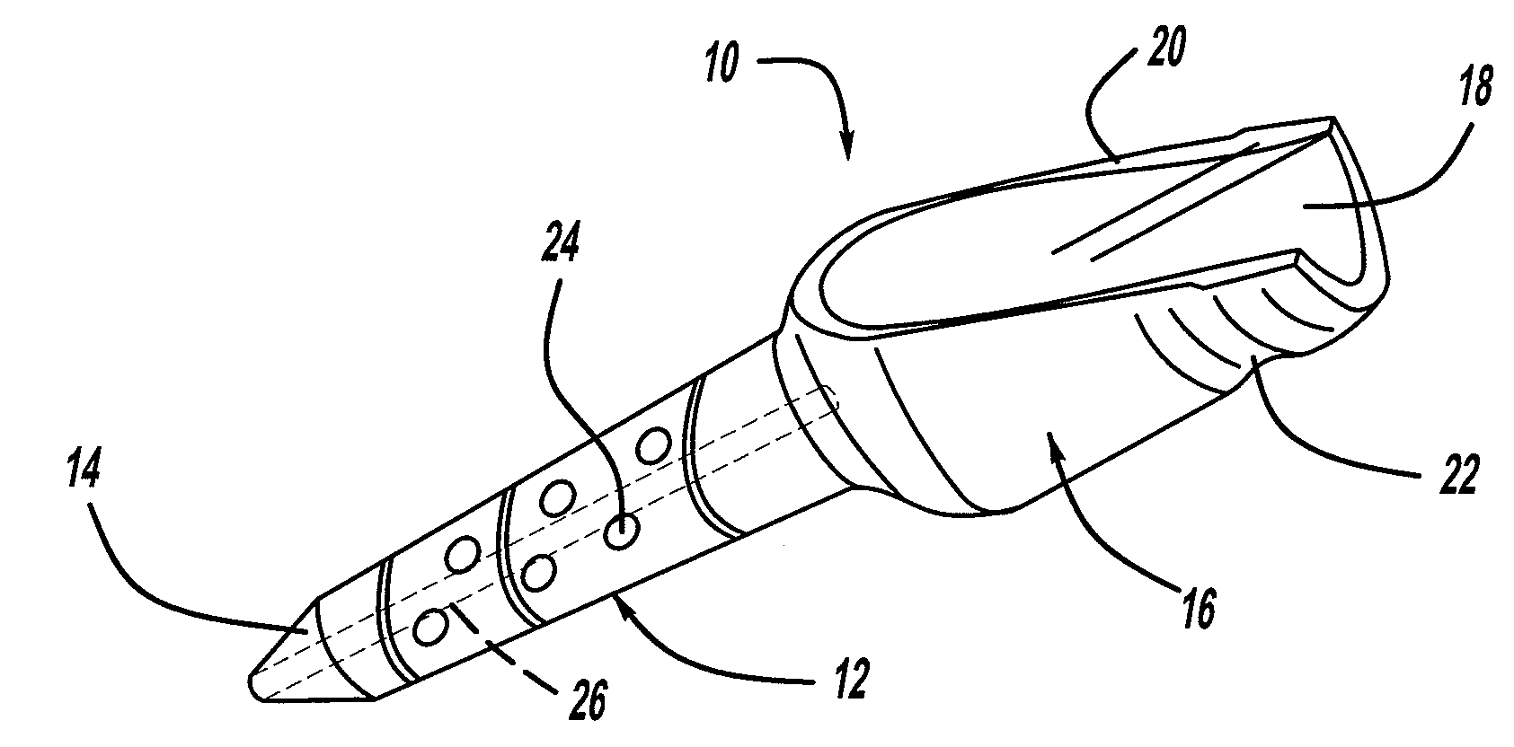
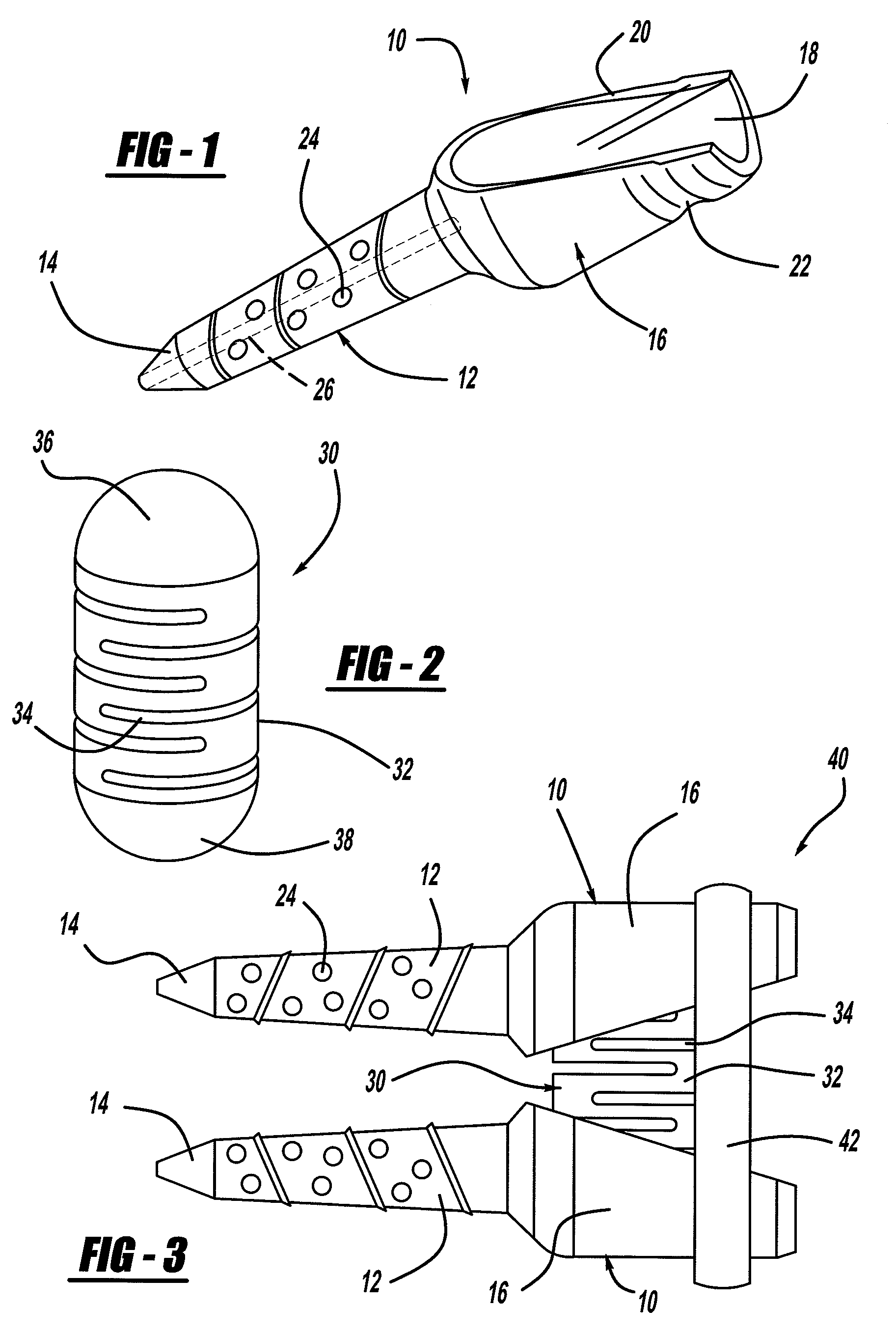
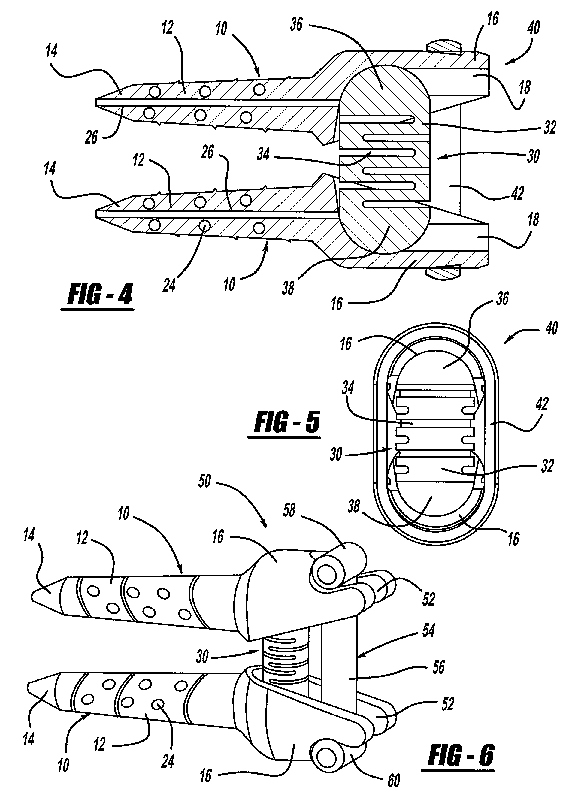
[0030]FIG. 1 is a perspective view of a pedicle screw 10 for use in a vertebral disc annular fibrosis tensioning and lengthening device (FIG. 3) of the invention. The pedicle screw 10 includes a threaded and tapered body portion 12 having a tip 14. The body portion 12 includes a plurality of holes 24 that allow bone to grow therein when the screw 10 is threaded into the vertebral body so that th...


PUM


Abstract

A surgical screw that includes a body portion that facilitates bone in-growth from a bone in which the screw is mounted so as to stabilize the screw in the bone. The body portion can have various configurations for facilitating bone in-growth, such as indentations, a roughened surface, such as by acid etching or abrasive media blasting, specialized coatings, such as hydroxyapetite, sintered beads, machined channels, etc. Because the body portion of the screw facilitates bone growth, the screw will be more firmly mounted to the bone so as to have a greater integrity in response to movement of the bone. The type of surgical screw can be any surgical screw that will benefit from being better anchored in bone, such as pedicle screws, long bone screws, cervical fusion screws, tendon anchoring screws, etc.

Description

CROSS-REFERENCE TO RELATED APPLICATIONS[0001]This application is a continuation-in-part application of U.S. patent application Ser. No. 11 / 646,750, filed Dec. 28, 2006, titled “Vertebral Disc Annular Fibrosis Tensioning and Lengthening Device.”BACKGROUND OF THE INVENTION[0002]1. Field of the Invention[0003]This invention relates generally to a surgical screw and, more particularly, to a surgical screw that includes a body portion that facilitates bone in-growth.[0004]2. Discussion of the Related Art[0005]The human spine includes a series of vertebrae interconnected by connective tissue referred to as intervertebral discs that act as a cushion between the vertebrae. The discs allow for movement of the vertebrae so that the back can bend and rotate.[0006]The intervertebral disc is an active organ in which the normal and pathologic anatomies are well known, but the normal and pathologic physiologies have not been greatly understood. The intervertebral disc permits rhythmic motions requ...

Claims


Application Information

Patent Timeline
Patent Type & Authority Applications(United States)
IPC IPC(8): A61B17/70
CPCA61B17/7005A61B17/7007A61B17/7025A61B2017/8655A61B17/7028A61B17/8625A61B17/866A61B17/7026
Inventor PEREZ-CRUET, MIQUELANGELO J.PEPPER, JOHN R.MILLER, JOHN A.
Owner MI4SPINE
Why Eureka
Try Eureka