Use of so2 from flue gas for acid wash of ammonia

a flue gas and ammonia acid wash technology, applied in the direction of greenhouse gas reduction, emission prevention, separation processes, etc., can solve the problem of containing a substantial amount of ammonia, and achieve the effect of efficient and environmentally acceptabl

Active Publication Date: 2008-07-31
GENERAL ELECTRIC TECH GMBH
View PDF8 Cites 103 Cited by
  • Summary
  • Abstract
  • Description
  • Claims
  • Application Information

AI Technical Summary

Benefits of technology

[0007]An object of the present invention is to provide an efficient and envi

Problems solved by technology

A problem of the process described in WO 2006/022885 is that the clean flue ga

Method used


Image

  • Use of so2 from flue gas for acid wash of ammonia
  • Use of so2 from flue gas for acid wash of ammonia
  • Use of so2 from flue gas for acid wash of ammonia

Examples


Embodiment Construction

[0032]As used throughout the present description the unit “ppm” refers to parts per million on a volume basis.

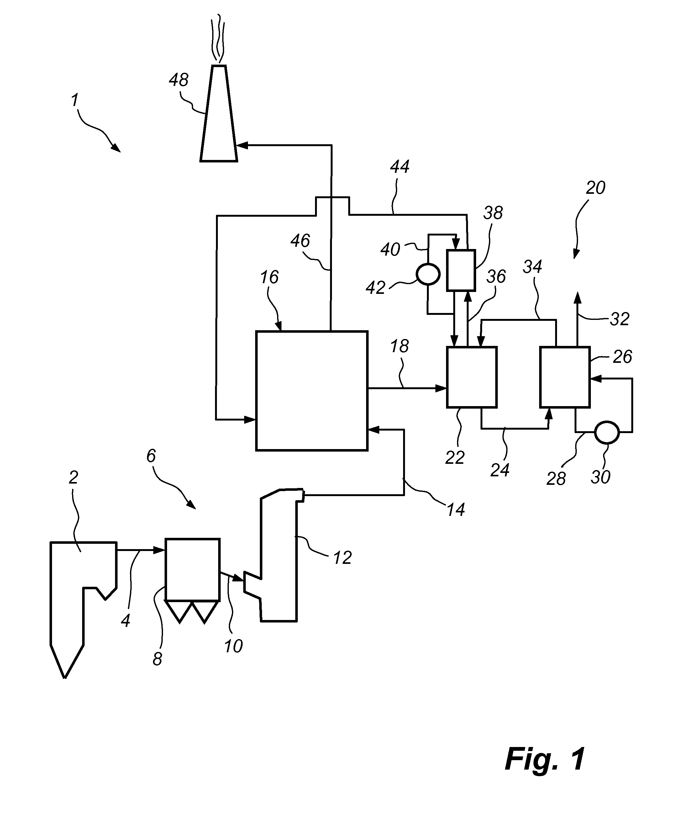
[0033]FIG. 1 is a schematic side view and illustrates a power plant 1, as seen from the side thereof. The power plant 1 comprises a boiler 2. During the combustion of a fuel, such as coal or oil, a hot process gas, often referred to as a flue gas, is generated in the boiler 2. The flue gas, which contains polluting substances, including dust particles, sulphur dioxide, SO2, sulphur trioxide, SO3, and carbon dioxide, CO2, leaves the boiler 2 via a gas duct 4. The gas duct 4 is operative for forwarding the flue gas to a conventional air pollution control system 6. The conventional air pollution control system 6 includes a dust collector 8, in the form of, e.g., an electrostatic precipitator, an example of which is described in U.S. Pat. No. 4,502,872. Furthermore, the conventional air pollution control system 6 comprises a duct 10 which is operative for forwarding the flue gas...


PUM

PropertyMeasurementUnit
Efficiencyaaaaaaaaaa
Energyaaaaaaaaaa

Abstract

A gas cleaning system, which is operative for cleaning a process gas containing carbon dioxide and sulphur dioxide, comprises a combined cooling and cleaning system (16), and a CO2-absorber. The combined cooling and cleaning system (16) comprises a first gas-liquid contacting device (50) located upstream of the CO2-absorber and operative for cooling the process gas by means of a cooling liquid, and for absorbing into the cooling liquid sulphur dioxide of the process gas, such that a cooling liquid containing sulphate is obtained. The combined cooling and cleaning system (16) further comprises a second gas-liquid contacting device (94) located downstream of the CO2-absorber and operative for removing ammonia from the process gas, which has been treated in the CO2-absorber, by means of bringing the process gas containing ammonia into contact with the cooling liquid containing sulphate.

Description

CROSS REFERENCE TO RELATED APPLICATION(S)[0001]This application claims priority to copending U.S. provisional application entitled, “USE OF SO2 FROM FLUE GAS FOR ACID WASH OF AMMONIA,” having Ser. No. US60 / 887,357, filed Jan. 31, 2007, the disclosure of which is entirely incorporated herein by reference.FIELD OF THE INVENTION[0002]The present invention relates to a method of cleaning a process gas containing carbon dioxide and sulphur dioxide, said method including removing, at least partly, carbon dioxide from the process gas by means of, in a first step, cooling the process gas, and, in a second step, bringing the cooled process gas into contact with an ammoniated solution or slurry absorbing at least a part of the carbon dioxide.[0003]The present invention also relates to a gas cleaning system which is operative for cleaning a process gas containing carbon dioxide and sulphur dioxide, said gas cleaning system comprising a combined cooling and cleaning system, which is operative f...

Claims


Application Information

Patent Timeline
IPC IPC(8): B01D53/30B01D47/00B01D47/10
CPCB01D53/1456Y02E20/363B01D53/62B01D53/75B01D2251/604B01D2252/102B01D2257/302B01D2257/504F23J15/006F23J15/04F23J15/06F23J2215/20F23J2215/50F23J2219/40Y02C10/04Y02C10/06B01D53/501Y02A50/20Y02C20/40Y02E20/32Y02E20/30B01D53/14B01D53/50
Inventor GAL, ELI
Owner GENERAL ELECTRIC TECH GMBH
Why Eureka
Try Eureka