Acceleration-sensing loader activation system and method

a technology of acceleration sensing and activation system, which is applied in the field of acceleration sensing loader activation system and method, can solve the problems of noise generation, noise generation, and noise generation, and the sound activation mechanism is also subject to errors

Inactive Publication Date: 2008-07-31
SMART PARTS
View PDF5 Cites 27 Cited by
  • Summary
  • Abstract
  • Description
  • Claims
  • Application Information

AI Technical Summary

Benefits of technology

[0004]When a paintball marker is activated or fired, a sequence of internal mechanical events occurs to propel the paintball out of the marker. The internal mechanical movements of the firing mechanism and the resulting release of the paintball create forces which cause movement (acceleration) of the marker body and attached paintball loader assembly during a shot sequence. By sensing these accelerations (such as by means of an acceleration sensor with appropriate sign

Problems solved by technology

Unfortunately, electronic “eyes” may have difficulty sensing the presence or absence of a paintball under various situations.
The optical sensors may also become dirty and have

Method used


Image

  • Acceleration-sensing loader activation system and method
  • Acceleration-sensing loader activation system and method
  • Acceleration-sensing loader activation system and method

Examples


Embodiment Construction

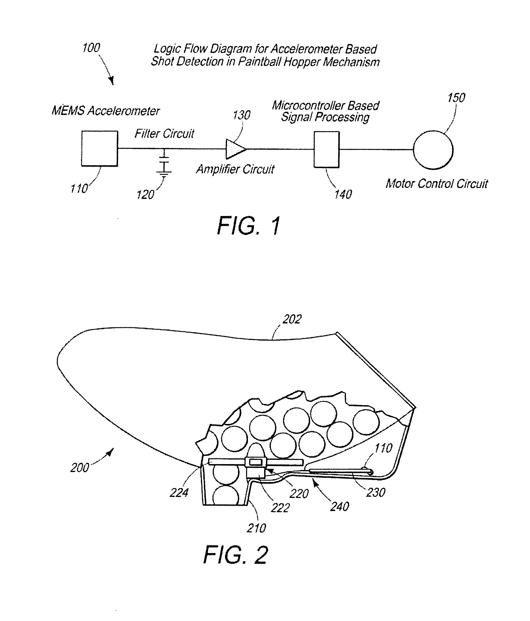
[0013]In the following detailed description, reference is made to the accompanying drawings, which form part thereof, and in which are shown, by way of illustration, exemplary, non-limiting embodiments illustrating various principles of the present invention and how it may be practiced.

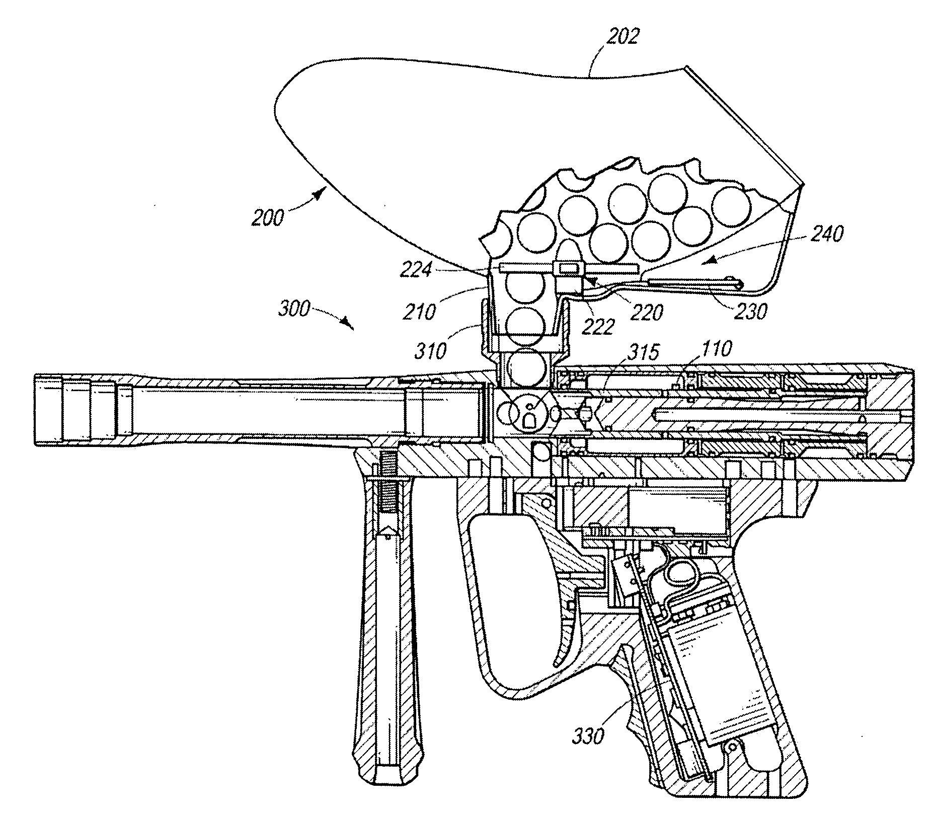
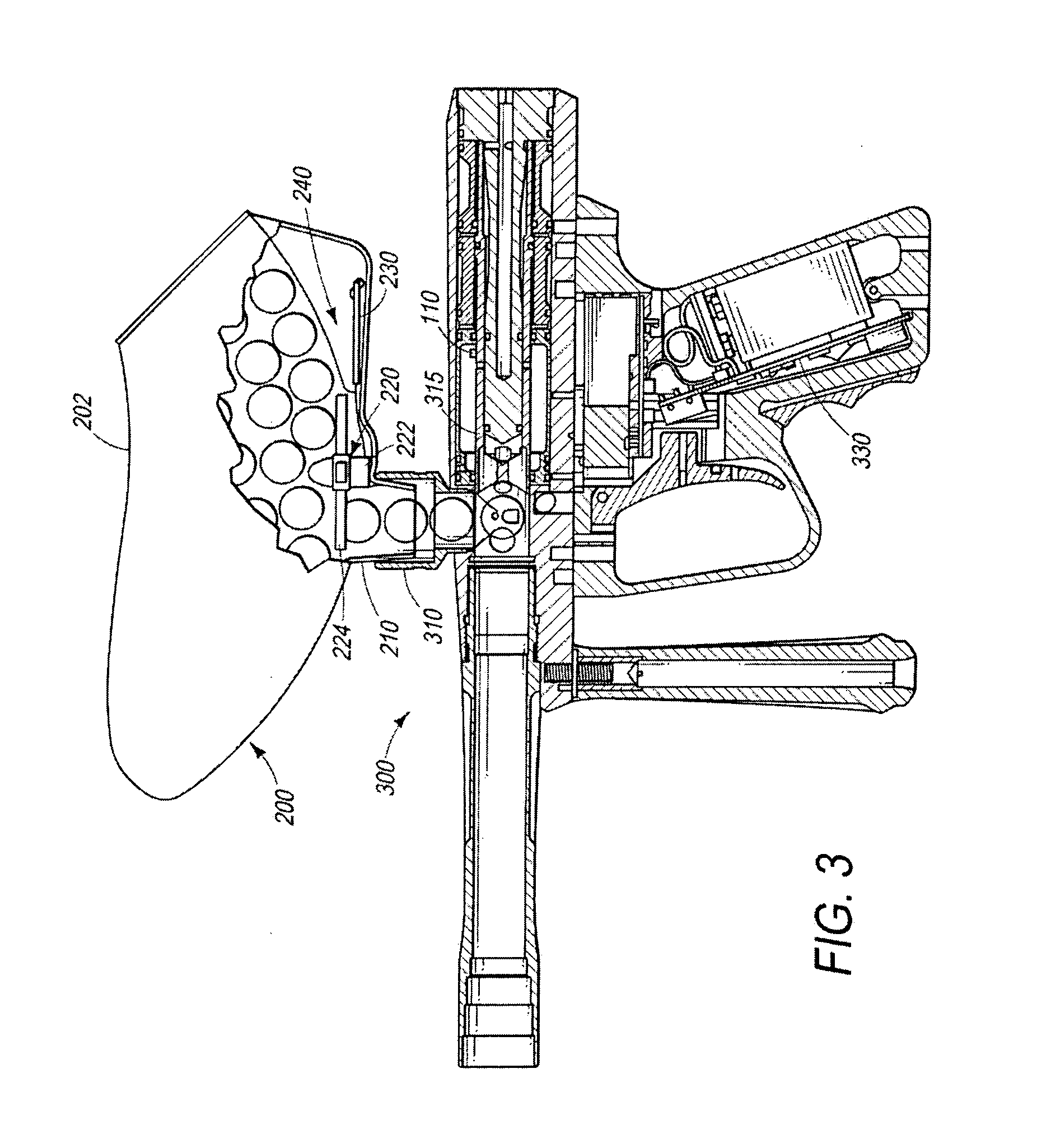
[0014]FIG. 1 is a schematic block diagram of a loader activation circuit 100 implementing an acceleration sensor 110 according to principles of the present invention. Referring to FIG. 1, a loader activation circuit 100 preferably includes an acceleration sensor 110 (e.g., a MEMS accelerometer), a filter circuit 120 (e.g., a RC low pass filter), an amplifier circuit 130 (e.g., an op-amp based amplifier), a signal processing circuit 140 (e.g., a microcontroller-based processor), and a motor control circuit 150 (e.g., a bidirectional DC motor control system).

[0015]The acceleration sensor 110 is preferably configured to detect movement of the loader, a paintball marker, and / or an operating component of t...


PUM


Abstract

An acceleration-sensing loader activation system can include an acceleration sensor configured to generate an electrical signal corresponding to the magnitude and periodicity of movement of a marker or loader body or a marker or loader component. A signal filter circuit can be arranged in communication with the acceleration sensor to receive and filter the electrical signal. A signal amplifier circuit can be arranged in communication with the signal filter circuit to amplify a signal from the signal filter circuit and transmit the amplified signal to a signal processing circuit. The signal processing circuit can be programmed to evaluate the incoming signal and determine whether it corresponds to a desired actuation event (such as a firing event). If the signal processing circuit determines that a desired actuation event has occurred, it can then send a control signal to a control circuit to activate a feed device of the loader. A method of activating a loader assembly preferably includes using an acceleration sensor to detect movement of a paintball marker or loader's operating mechanisms and/or body and to output an electrical signal proportional to the magnitude and periodicity of the movement. The resulting signal is then preferably processed using filtering, amplification, and digital signal processing circuitry to determine whether the movement corresponds to a desired actuation event and, if so, to provide an activation signal to activate a loading operation of the paintball loader's internal feed mechanism.

Description

PRIORITY CLAIM[0001]This application is a non-provisional application of and claims priority from copending U.S. Provisional Patent Application No. 60 / 886,605, filed Jan. 25, 2007, the contents of which are incorporated herein by reference in their entirety.TECHNICAL FIELD[0002]The present invention relates to mechanisms and methods for activating a motor or other agitator or feed system in a paintball marker loader. In particular, this invention relates to a method and mechanism for sensing a firing or other operation of the paintball marker and activating the loader in response thereto.BACKGROUND OF THE INVENTION[0003]Present day paintball markers are capable of high rates of fire. Higher firing rates also, however, require faster loading rates in order to provide a sufficient supply of paintballs to the paintball marker. Conventional loaders have utilized various methods and mechanisms to assist in feeding paintballs from the loader into the paintball marker at higher speeds. Typ...

Claims


Application Information

Patent Timeline
IPC IPC(8): F41B15/00
CPCF41B11/53F41A9/01
Inventor MOORE, JAMIEKNUTH, ROCKY
Owner SMART PARTS
Why Eureka
Try Eureka