Impeller for a wearable positive airway pressure device

a positive airway and pump technology, applied in the direction of medical devices, non-positive displacement pumps, liquid fuel engines, etc., can solve the problems of obstructing the upper airway, daytime sleepiness and chronic fatigue, and 50% of patients prescribed pap treatment use their device regularly

Inactive Publication Date: 2008-07-31
BRAEBON MEDICAL CORP
View PDF22 Cites 68 Cited by
  • Summary
  • Abstract
  • Description
  • Claims
  • Application Information

AI Technical Summary

Problems solved by technology

The condition is caused by relaxation of the soft tissue in the palate during sleep, resulting in obstruction of the upper airway.
The obvious side effects of sleep apnea are daytime sleepiness and chronic fatigue.
Although positive airway pressure is known to be an effective treatment for OSA, only 50% of patients prescribed PAP treatment use their device regularly.
According to patient studies, the primary reason for this lack of compliance is that patients find the devices cumbersome and uncomfortable to wear.
The size, weight, and alternating current (AC) power requirement restrict the patient's freedom for travel with the device, and freedom for movement while in bed.
During use, patient movement frequently causes the tubing to tug on the interface, which may wake the patient.
Tugging on the interface may also cause improper fit of the device, resulting in loss of effectiveness of the treatment and increased noise of the device due to air leakage.
The 6-foot hose that normally connects the PAP device to the patient interface may also restrict body movement.
The above factors are all likely to cause frequent patient arousal during the night, and contribute to the low level of compliance of PAP treatment.
In spite of the reduced size, increased portability, and quieter operation of modern devices compared to their predecessors, inconvenience and awkwardness remain significant contributors to low patient compliance.
The most significant obstacle to making devices used in treatment of sleep-disordered breathing portable is the high power consumption of the blower unit, therefore requiring a large and heavy stored energy device (i.e. battery).

Method used


Image

  • Impeller for a wearable positive airway pressure device
  • Impeller for a wearable positive airway pressure device
  • Impeller for a wearable positive airway pressure device

Examples


first embodiment

[0047]FIG. 5a shows a front view of an impeller according to the present invention. The impeller 160 includes a hub 164 and a plurality of radial blades or vanes 122 and 122′ arranged in an annular array on the face of the impeller disc 160. In the illustrative example, vanes 122 extend radially outwardly from the hub 164 to the periphery of the impeller disc 160. Alternating vanes 122′ are optionally shorter in length and extend radially outwardly from the vicinity of the middle portion of the impeller disc 160 to the periphery thereof. The vanes 122 have end portions with leading edges 122a and trailing edges 122b respectively. The leading and trailing edges 122a, 122b of the vanes 122 are defined as the edges of the vanes 122 in the proximity of the hub 164 and the periphery of the impeller disc 160, respectively. The vanes 122′ have similar leading and trailing edges. FIG. 5b is a side view of the impeller shown in FIG. 5a. At least one of the end portions of the vanes is curved...

second embodiment

[0052]In the present invention, the output pressure of a rotary air pump in a PAP device is increased by successively accelerating air ingested by the blower, first in the axial direction followed by a second acceleration in the radial direction as shown in FIGS. 8a and 8b.

[0053]The impeller 260 shown in FIG. 8a is similar to the impeller 160 shown in FIG. 5a. The impeller 260 comprises a hub 264 and a plurality of radial blades or vanes 222 and 222′ arranged in an annular array on the face of the impeller disc 260. Similar to the first embodiment, in the illustrative example, vanes 222 extend radially outwardly from the hub 264 to the periphery of the impeller disc 260. Alternating vanes 222′ optionally extend radially outwardly from the vicinity of the middle portion of the impeller disc 260 to the periphery thereof. The vanes 222 have end portions with leading edges 222a and trailing edges 222b respectively. The leading edges 222a and trailing edges 222b of the vanes 222 are def...

third embodiment

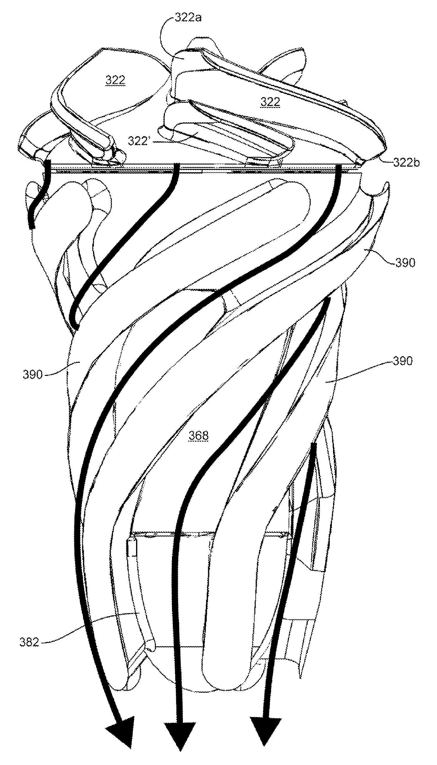
[0055]In the present invention, the output pressure of a rotary air pump in a PAP device is increased by successively accelerating air ingested in a substantially axial direction, a substantially radial direction and finally again in a substantially axial direction. This is achieved by combining the geometries of the vanes 122, 122′ and vanes 222 and 222′.

[0056]The impeller 360 shown in FIG. 10 is similar to the impeller 260 shown in FIG. 8a. The impeller 360 includes a hub 364 and a plurality of blades or vanes 322 and 322′ arranged in an annular array on the face of the impeller disc 360. Similar to the first and second embodiments, in the illustrative example, vanes 322 extend radially outwardly from the hub 364 to the periphery of the impeller disc 360. Alternating vanes 322′ optionally extend radially outwardly from the vicinity of the middle portion of the impeller disc 360 to the periphery thereof. The vanes 322 have opposite longitudinal edges, a base edge 323 at which they ...


PUM


Abstract

A method for increasing output pressure of a blower unit in a Positive Airway Pressure (PAP) device, the blower unit having a blower rotatable about an axis of rotation. The method includes the steps of ingesting air into the blower unit, successively accelerating the ingested air in a direction substantially radial to the axis of rotation and a direction substantially parallel to the axis of rotation for generating a flow of compressed air; and exhausting the accelerated air from the blower unit. A PAP device with the improved blower generates increased air pressure compared to prior art devices or produces at least the same air pressure at a reduced size.

Description

FIELD OF THE INVENTION[0001]The present invention relates generally to an impeller for positive air pressure devices. More particularly, the present invention relates to an impeller for wearable positive air pressure devices.BACKGROUND OF THE INVENTION[0002]Obstructive sleep apnea (OSA) is a condition that affects an estimated 14 million Americans. The condition is caused by relaxation of the soft tissue in the palate during sleep, resulting in obstruction of the upper airway. OSA is characterized by a complete cessation of breathing during sleep for 10 or more seconds (apnea), or a reduction in breathing for 10 or more seconds causing a 4% or greater decrease in blood oxygen level (hypopnea). Individuals having five or more apneic or hypopneic events per hour are diagnosed as suffering from OSA. The obvious side effects of sleep apnea are daytime sleepiness and chronic fatigue. However, OSA is known to be a contributing factor in hypertension, heart disease, as well as other seriou...

Claims


Application Information

Patent Timeline
Patent Type & Authority Applications(United States)
IPC IPC(8): A61M16/00
CPCA61M16/0066A61M16/0683A61M2210/0618A61M2209/088A61M2205/8206A61M16/0069A61M16/107F04D29/281F04D29/30F04D25/082F04D17/06F04D29/444F05D2250/52F04D29/4233F04D29/5806
Inventor ROBERTS, STEPHEN KEIRBRADLEY, DONALD CARMON
Owner BRAEBON MEDICAL CORP
Why Eureka
Try Eureka