Thermal activation printer

a printer and activation technology, applied in the field of thermal activation printers, can solve the problems of increasing the size of the apparatus as a whole, and the inability to apply temporary stock parts, and achieve the effects of smooth transportation of sheet materials, and reducing the size of the apparatus

Inactive Publication Date: 2008-07-31
SEIKO INSTR INC
View PDF6 Cites 6 Cited by
  • Summary
  • Abstract
  • Description
  • Claims
  • Application Information

AI Technical Summary

Benefits of technology

[0011]It is an object of the present invention to provide a thermal activation printer with which it is possible to downsize an apparatus as a whole.
[0013]In the thermal activation printer according to the present invention structured as described above, because the reversing portion and the stock portion of the temporary stock means are formed along the inner peripheral portion of the casing covering the temporary stock means, an inner space of the casing is effectively used, thereby downsizing an apparatus as a whole. In the thermal activation printer, the sheet material transported to the reversing portion of the temporary stock means is transported to the stock portion having a straight line shape, thereby allowing the sheet material to be temporarily stocked in the flat state without being curved. Therefore, with the temporary stock means, the sheet material temporarily stocked by the temporary stock means is prevented from causing such a tendency that the sheet material is curved in a lengthwise direction. Further, with the thermal activation printer, the temporary stock means has the reversing portion, thereby making it possible to stock the sheet material of a relatively large length without increasing a size of the apparatus as a whole.
[0015]At least one of the transport path of the reversing portion and the stock portion included in the thermal activation printer according to the present invention is preferably provided with a transport roller for transporting the sheet material. With this structure, smooth transportation of the sheet material is enabled, and the sheet material is stocked in a favorable manner.
[0016]Further, the reversing portion of the temporary stock means included in the thermal activation printer according to the present invention may be provided with a transport roller having an outer peripheral surface forming a transport path. With this structure, the temporary stock means enables smooth transportation of the sheet material, and the sheet material is stocked in a favorable manner.
[0017]Further, the stock portion of the temporary stock means included in the thermal activation printer according to the present invention is preferably formed in a tapered shape having a gap in a thickness direction of the sheet material, the gap gradually becoming larger from the reversing portion side along the transport direction of the sheet material. With this structure, a slide resistance between the sheet material entering inside the stock portion and an inside of the stock portion is suppressed, and the sheet material is smoothly transported from the transport path of the reversing portion into the stock portion.
[0018]As described above, with the thermal activation printer according to the present invention, it is possible to downsize an apparatus as a whole.

Problems solved by technology

Therefore, there is a problem of inviting increase in size of the apparatus as a whole.
Thus, it is impossible to apply the temporary stock portions as disclosed in Patent Documents 1 and 2 to small mobile printers which can easily be carried by one hand.

Method used


Image

  • Thermal activation printer
  • Thermal activation printer
  • Thermal activation printer

Examples


first embodiment

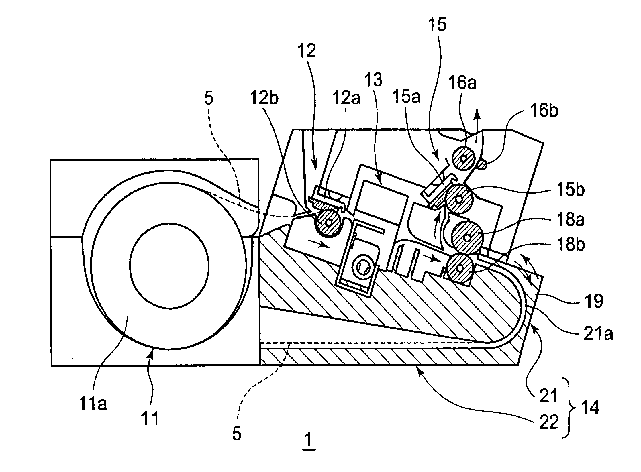
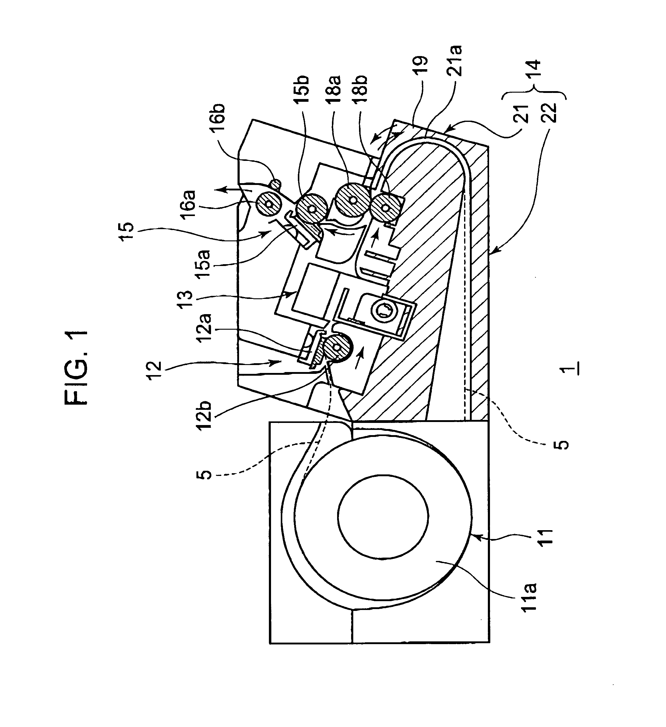
[0026]As shown in, FIG. 1, a label issuing apparatus 1 according to this embodiment includes, along a transport direction of a sheet material 5 indicated by arrows of FIG. 1, a sheet supplying portion 11 for supplying the sheet material 5, a printing portion 12 for printing various information such as characters on a heat-sensitive printing layer of the sheet material 5, a cutting portion 13 for cutting the sheet material 5, on which the printing has been performed by the printing portion 12, into a predetermined length, a temporary stock portion 14 for temporarily stocking the sheet material 5 on which the printing has been performed by the printing portion 12, a thermally activating portion 15 for heating a heat-sensitive adhesive layer of the sheet material 5 supplied from the temporary stock portion 14 to generate an adhesion force, and a pair of delivery rollers 16a and 16b for delivering the sheet material 5 to an outside of the apparatus.

[0027]In the sheet supplying portion 1...

second embodiment

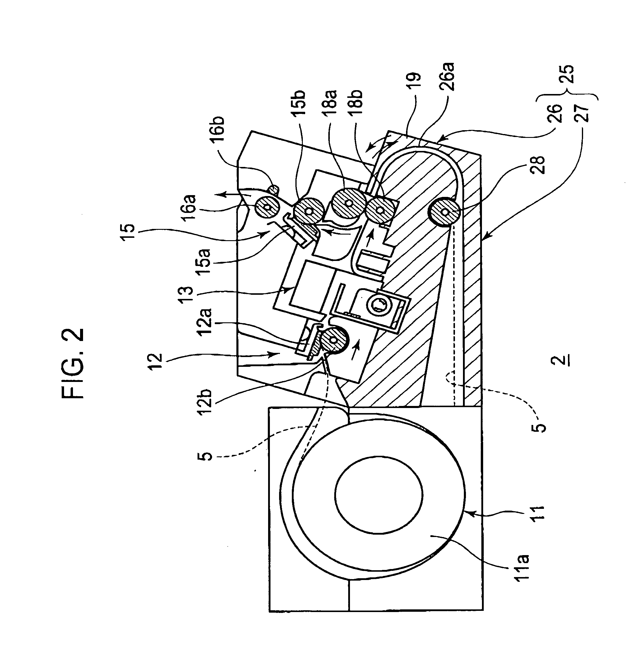
[0046]As shown in FIG. 2, a temporary stock portion 25 included in a label issuing apparatus 2 of a second embodiment of the present invention includes a reversing portion 26 having a transport path 26a having an arc shape, for reversing the transport direction of the sheet material 5 transported from the printing portion 12 and a stock portion 27 having a straight line shape, for temporarily stocking the sheet material 5, which is transported from the reversing portion 26, in a flat state.

[0047]In the reversing portion 26, at an end portion on the stock portion 27 side of the transport path 26a, there is disposed a transport roller 28 for transporting the sheet material 5. The transport roller 26 is rotated in synchronism with the transport rollers 18a and 18b by a rotation drive mechanism (not shown), thereby smoothly transporting the sheet material 5 from the reversing portion 26 to the stock portion 27.

[0048]The stock portion 27 is provided continuously to the reversing portion ...

third embodiment

[0052]As shown in FIG. 3, a temporary stock portion 30 included in a label issuing apparatus 3 of a third embodiment of the present invention includes a reversing portion 31 having a transport path 31a having an arc shape, for reversing the transport direction of the sheet material 5 transported from the printing portion 12 and a stock portion 32 having a straight line shape, for temporarily stocking the sheet material 5, which is transported from the reversing portion 31, in a flat state.

[0053]In order to transport the sheet material 5, which is transported from the printing portion 12 side, to the reversing portion 21 and to transport the sheet material 5, which is temporarily stocked, to the thermally activating portion 15, the reversing portion 31 includes the transport roller 18a and a transport roller 33 having an outer peripheral surface brought into contact with the transport roller 18a. The transport roller 33 is formed to have a diameter of about 20 mm and the transport pa...


PUM


Abstract

The present invention includes: a printing portion (12) for performing printing on a printing layer of a sheet material (5) including a sheet-like base having one surface provided with the printing layer and another surface provided with a heat-sensitive adhesive layer; a thermal activation portion (15) for heating the heat-sensitive adhesive layer of the sheet material (5) and generating an adhesive force; a temporary stock portion (14), which is disposed in a transport path for the sheet material (5) between the printing portion (12) and the thermal activation portion (15), for temporarily stocking the sheet material (5); and a casing (19) covering the temporary stock portion (14). The temporary stock portion (14) includes a reversing portion (21) provided with a transport path (21a) having an arc shape, for reversing a transport direction of the sheet material (5) transported from the printing portion (12) and a stock portion (22), which has a straight line shape and is provided continuously to the reversing portion (21), for stocking the sheet material (5) in a flat state, the reversing portion (21) and the stock portion (22) being formed along an inner peripheral portion of the casing (19).

Description

BACKGROUND OF THE INVENTION[0001]1. Field of the Invention[0002]The present invention relates to a thermal activation printer in which a heat-sensitive adhesive layer of a sheet material is heated to generate an adhesion force after temporarily stocking a sheet material on which printing has been performed.[0003]2. Description of the Related Art[0004]As a label used by being stuck to goods, there is known a label including a sheet-like base having one surface provided with a printing layer and another surface provided with a heat-sensitive adhesive layer.[0005]The printer for printing the label having the heat-sensitive adhesive layer as described above generally includes a sheet supplying device for supplying the sheet material, a printing device for printing various information on a printing layer of the sheet material supplied from the sheet supplying device, a cutting device for cutting the sheet material on which printing has been performed by the printing device, and a thermal...

Claims


Application Information

Patent Timeline
Patent Type & Authority Applications(United States)
IPC IPC(8): B65C9/25B41J2/32H05B1/00B41J3/407B41J11/00
CPCB41J2/32B65C2009/005B65C11/066B65C11/0289B65C9/25B65C9/1803B26D1/085B41J2/355B41J3/4075B41J15/165
Inventor KOHIRA, HIROYUKI
Owner SEIKO INSTR INC
Why Eureka
Try Eureka