
Image Illumination And Capture In A Scanning Device

a scanning device and image technology, applied in the field of scanning methods, can solve the problems of complex devices, inability to meet other requirements, complicated devices, and inability to accurately capture images, and achieve the effect of reducing the volume of the scanning devi

Inactive Publication Date: 2008-07-31
LEXMARK INT INC
View PDF22 Cites 24 Cited by
  • Summary
  • Abstract
  • Description
  • Claims
  • Application Information

AI Technical Summary

Benefits of technology

[0010]The present application is directed to embodiments of scanning devices and method of use that permit the capture of high resolution images of an original that is illuminated by a light source that is located outside of the optical field of view of an image detector. The light source may include individually selectable colors, such as red, green, and blue LEDs. In one aspect, the image detector may be a monochrome sensor that sequentially captures different color plane images of an original tha...

Problems solved by technology

Quality scans require intricate mechanisms which are often costly and complex.
A device meeting other requirements may not be acceptable because of an higher price.
Unfortunately, the relatively large field of view creates space and illumination complications.
Further, stray reflections may be prone to enter the field of view and reach the sensor.

Method used


Image

  • Image Illumination And Capture In A Scanning Device
  • Image Illumination And Capture In A Scanning Device
  • Image Illumination And Capture In A Scanning Device

Examples


Embodiment Construction

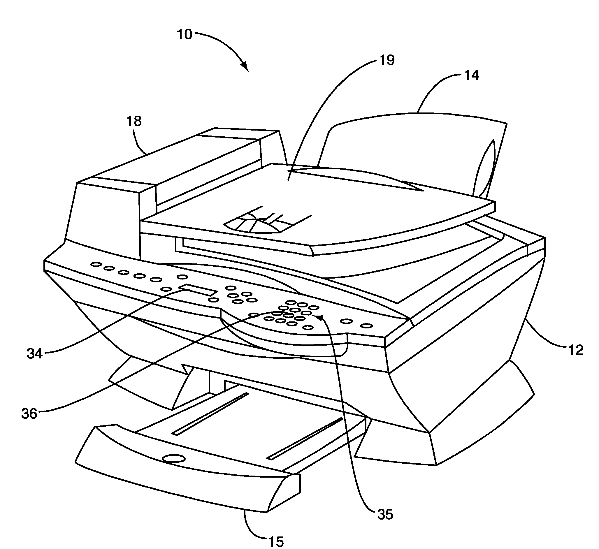
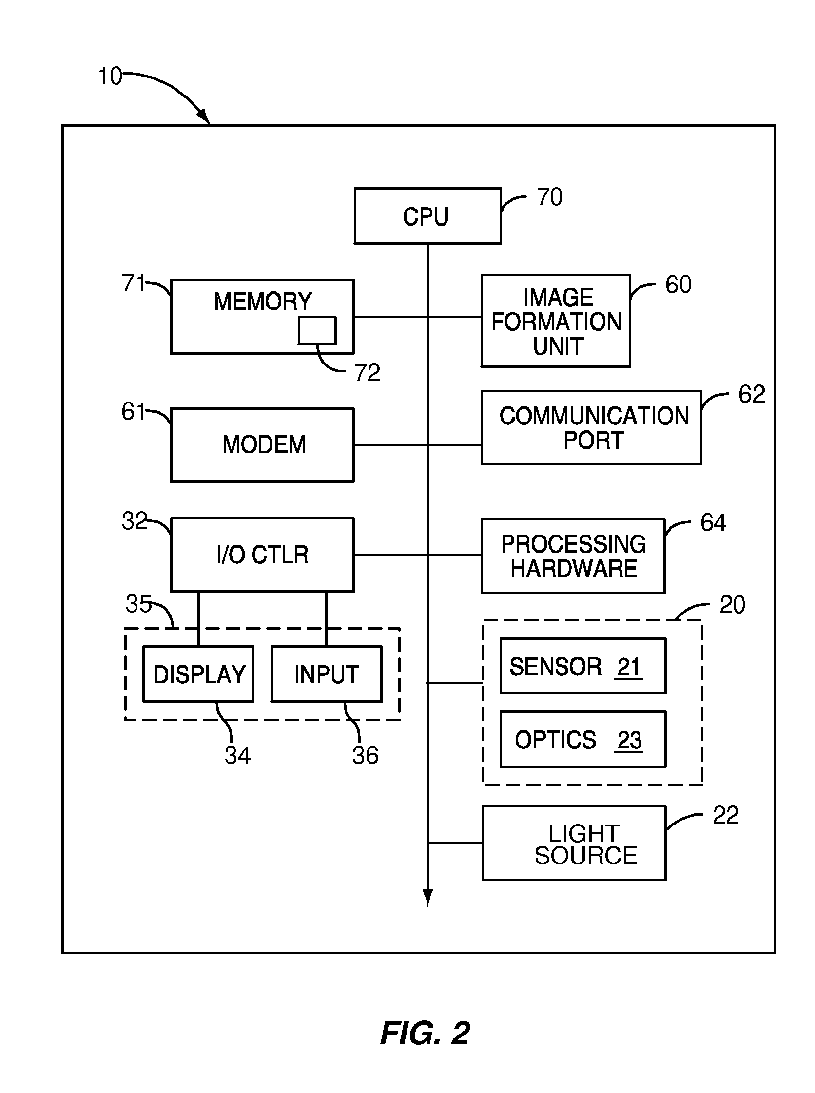
[0024]The present application discloses embodiments for using an imaging unit within a scanning device. The scanning device includes an imaging unit and a target bed for placement of the target document. The scanning device may include an illumination system that limits an amount of stray light that reaches an image sensor. Further, the scanning device may include a compact optics package that accommodates image sensors with lengthy focal lengths in a relatively small volume.

[0025]Spatially relative terms such as “under”, “below”, “lower”, “over”, “upper”, and the like, are used for ease of description to explain the positioning of one element relative to a second element. These terms are intended to encompass different orientations of the device in addition to different orientations than those depicted in the figures. Further, terms such as “first”, “second”, and the like, are also used to describe various elements, regions, sections, etc and are also not intended to be limiting. L...


PUM


Abstract

Scanning devices and method of use that permit the capture of high resolution images of an original that is illuminated by a light source that is located outside of the optical field of view of an image detector. In one aspect, the image detector may be a monochrome sensor that sequentially captures different color plane images of an original that is illuminated by different colors. The different color plane images may be processed to generate a full color copy of the original. Light and images may be directed through tapered optical waveguides to minimize the volume of the scanning device. The image detector may include a first associated waveguide while the light source may include a second associated waveguide.

Description

CROSS REFERENCES TO RELATED APPLICATIONS[0001]None.STATEMENT REGARDING FEDERALLY SPONSORED RESEARCH OR DEVELOPMENT[0002]None.REFERENCE TO SEQUENTIAL LISTING, ETC.[0003]None.BACKGROUND[0004]1. Field of the Invention[0005]The present invention relates generally to scanners and scanning methods, and more particularly to those permitting the capture of high resolution images of an original that is illuminated by a light source that is located outside of the optical field of view of an image detector.[0006]2. Description of the Related Art[0007]Scanning devices are used in a variety of applications. Scanning devices may be combined in an all-in-one unit that includes scanning, printing, and facsimile function. Scanning devices may also be independent and only capable of scanning documents. Historically, scanning devices include a drive mechanism that moves a scan bar across a target document. Each line of the document is individually scanned and the data is downloaded to a processor. Thi...

Claims


Application Information

Patent Timeline
IPC IPC(8): H04N1/04H04N1/46
CPCH04N1/02815H04N1/02855H04N1/02865H04N1/193H04N1/195H04N1/484G06F15/02H04N1/1013
Inventor MILLER, MARK ERICKING, ANTHONY MICHAELCHELVAYOHAN, MAHESAN
Owner LEXMARK INT INC
Learn More