Bent type zoom optical system and imaging system using the same
a technology of optical system and optical system, applied in the field of bent-type zoom optical system and imaging system, can solve the problems of not slimming down, difficult to ensure optical performance, obstacle to size reduction, etc., and achieve the effect of maximum zooming effect and maximum zooming
- Summary
- Abstract
- Description
- Claims
- Application Information
AI Technical Summary
Benefits of technology
Problems solved by technology
Method used
Image

Examples
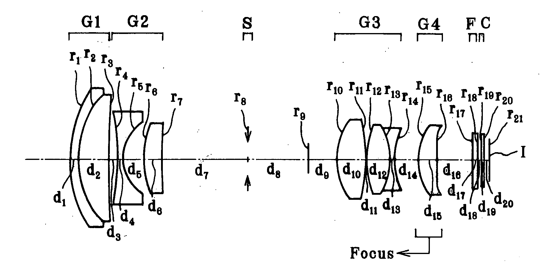
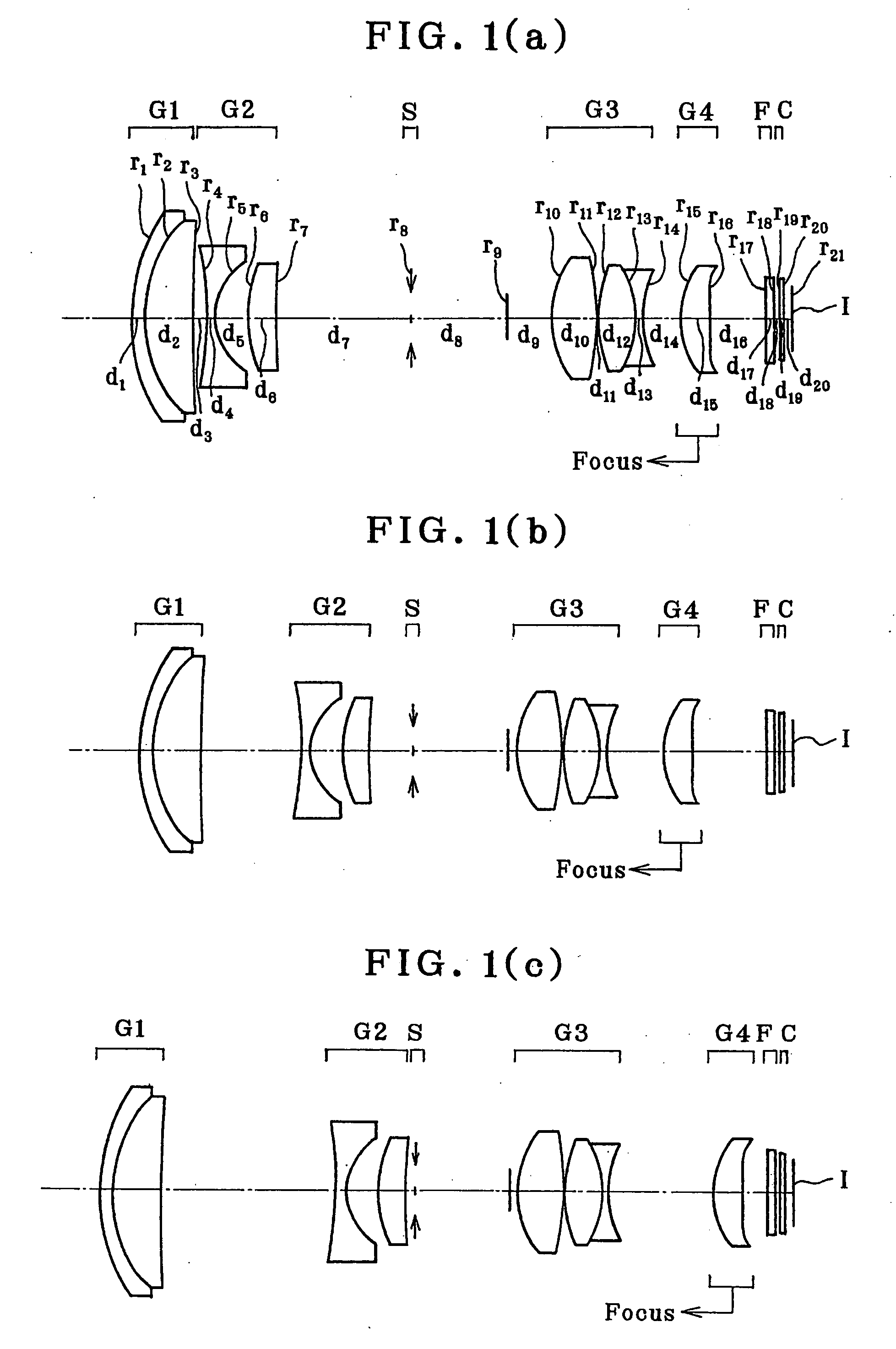
example 1
[0143]
r1 = 20.208d1 = 1.40nd1 = 1.92286νd1 = 20.88r2 = 14.652d2 = 5.14nd2 = 1.69350νd2 = 53.20r3 = 331.987d3 = (Variable)(Aspheric)r4 = −23.029d4 = 1.00nd3 = 1.80610νd3 = 40.92(Aspheric)r5 = 5.924 (Aspheric)d5 = 3.57r6 = 15.713d6 = 2.71nd4 = 1.92286νd4 = 18.90r7 = 57.508d7 = (Variable)r8 = ∞ (Stop)d8 = 10.00r9 = ∞ (HPP)d9 = (Variable)r10 = 10.162d10 = 5.00nd5 = 1.58913νd5 = 61.25(Aspheric)r11 = −20.305d11 = 0.20(Aspheric)r12 = 15.967d12 = 3.92nd6 = 1.57250νd6 = 57.74r13 = −10.788d13 = 0.65nd7 = 1.90366νd7 = 31.31r14 = 10.669d14 = (Variable)r15 = 12.041d15 = 3.00nd8 = 1.58313νd8 = 59.46(Aspheric)r16 = −192.547d16 = (Variable)(Aspheric)r17 = ∞d17 = 0.85nd9 = 1.54771νd9 = 62.84r18 = ∞d18 = 0.50d19 = ∞d19 = 0.50nd10 = 1.51633νd10 = 64.14r20 = ∞d20 = 1.00r21 = ∞(Imaging plane)Aspherical Coefficients3rd surfaceK = 0.000A4 = 8.10303 × 10⁻⁶A6 = −4.28147 × 10⁻⁹A8 = −6.76544 × 10⁻¹¹A10 = 3.65815 × 10−134th surfaceK = 0.000A4 = 3.48094 × 10⁻⁴A6 = −3.52662 × 10⁻⁶A8 = −2.69430 × 10⁻⁸A10 = 6.7290...
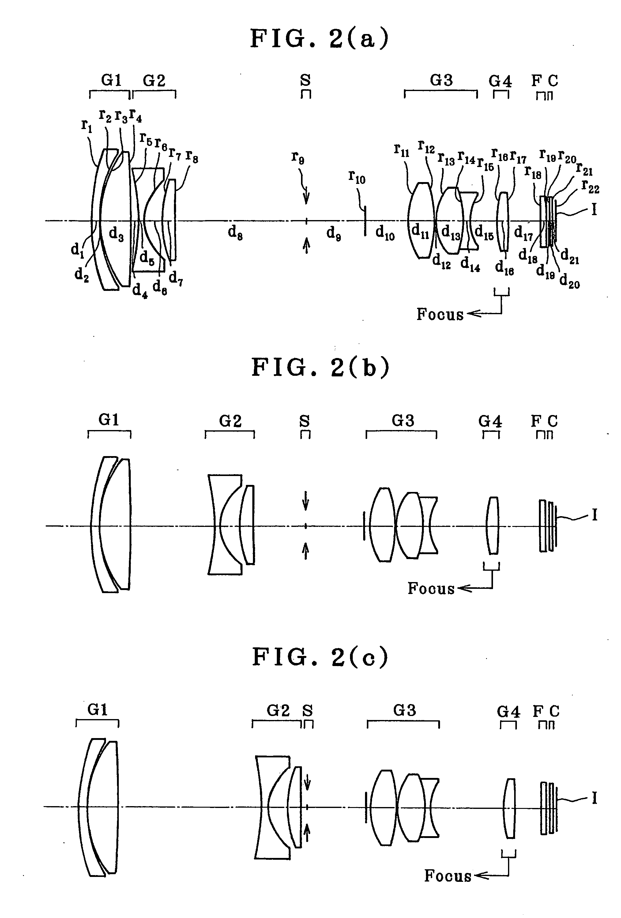
example 2
[0144]
r1 = 34.215d1 = 1.45nd1 = 1.80810νd1 = 22.76r2 = 22.187d2 = 0.10r3 = 19.116d3 = 5.10nd2 = 1.58913νd2 = 61.28r4 = −112.861d4 = (Variable)(Aspheric)r5 = −20.825d5 = 1.00nd3 = 1.80610νd3 = 40.92(Aspheric)r6 = 7.450 (Aspheric)d6 = 3.20r7 = 21.082d7 = 2.05nd4 = 1.92286νd4 = 18.90r8 = 204.903d8 = (Variable)r9 = ∞ (Stop)d9 = 10.00r10 = ∞ (HPP)d10 = (Variable)r11 = 11.707d11 = 4.35nd5 = 1.58913νd5 = 61.28(Aspheric)r12 = −22.192d12 = 0.20(Aspheric)r13 = 9.203d13 = 4.44nd6 = 1.49700νd6 = 81.54r14 = −17.989d14 = 0.97nd7 = 1.90366νd7 = 31.31r15 = 7.821d15 = (Variable)r16 = 17.634d16 = 2.00nd8 = 1.52542νd8 = 55.78(Aspheric)r17 = −61.206d17 = (Variable)r18 = ∞d18 = 0.85nd9 = 1.54771νd9 = 62.84r19 = ∞d19 = 0.50r20 = ∞d20 = 0.50nd10 = 1.51633νd10 = 64.14r21 = ∞d21 = 0.60r22 = ∞(Imaging plane)Aspherical Coefficients4th surfaceK = 0.000A4 = 1.13511 × 10⁻⁵A6 = −1.07450 × 10⁻⁸A8 = 6.85102 × 10⁻¹¹A10 = −1.05519 × 10−135th surfaceK = 0.000A4 = 2.18566 × 10⁻⁴A6 = −2.82940 × 10⁻⁷A8 = −2.24959 × 10⁻⁸A...
example 3
[0145]
r1 = 244.854d1 = 1.15nd1 = 1.92286νd = 20.88r2 = 38.880d2 = 0.10r3 = 21.300d3 = 3.39nd2 = 1.74330νd = 49.33r4 = −51.449 (Aspheric)d4 = (Variable)r5 = −21.640 (Aspheric)d5 = 0.90nd3 = 1.80610νd = 40.92r6 = 7.060 (Aspheric)d6 = 1.76r7 = 11.751d7 = 2.05nd4 = 1.92286νd = 20.88r8 = 24.727d8 = 0.50r9 = ∞ (HPP)d9 = 10.20r10 = ∞ (HPP)d10 = (Variable)r11 = ∞ (Stop)d11 = 0.40r12 = 10.274 (Aspheric)d12 = 2.80nd5 = 1.58313νd = 59.46r13 = −29.469 (Aspheric)d13 = 0.16r14 = 9.245d14 = 3.83nd6 = 1.48749νd = 70.23r15 = −52.560d15 = 0.26r16 = 199.572d16 = 0.55nd7 = 1.83400νd = 37.16r17 = 6.042d17 = (Variable)r18 = −17.085d18 = 0.65nd8 = 1.84666νd = 23.78r19 = 26.750d19 = 0.10r20 = 10.841 (Aspheric)d20 = 3.14nd9 = 1.69350νd = 53.20r21 = −10.117 (Aspheric)d21 = (Variable)r22 = ∞d22 = 1.00nd10 = 1.51633νd = 64.14r23 = ∞d23 = 0.50r24 = ∞d24 = 0.50nd11 = 1.51633νd = 64.14r25 = ∞d25 = 0.60r26 = ∞ (Imaging plane)Aspherical Coefficients4th surfaceK = 0.000A4 = 2.44242 × 10⁻⁵A6 = −3.45144 × 10⁻⁸A8 = 0A1...
PUM
 Abstract
Description
Claims
Application Information