CPP magnetic recording head with self-stabilizing vortex configuration

a recording head and self-stabilizing technology, applied in the field of self-stabilizing vortex configuration of cpp magnetic recording head, can solve the problems of more severe and immediate problems, the noise of barkhausen noise in the sensor signal, and the stabilization of its magnetically free layer, so as to reduce the risk of side-reading, and reduce the effect of side-reading

Inactive Publication Date: 2008-07-31
HEADWAY TECH INC
View PDF20 Cites 25 Cited by
  • Summary
  • Abstract
  • Description
  • Claims
  • Application Information

AI Technical Summary

Benefits of technology

[0015]The third object of this invention is to provide such a read sensor in which the sensor shields can be more closely formed about the sensor, thereby eliminating side-reading and providing generally more effective shielding of the element.
[0016]The fourth object of this invention is to provide a sensor with a thinner stack and less space between upper and lower shields, to improve the reading of high density media.
[0017]A fifth object of the present invention is to provide a sensor in which free layer stability is improved as the sensor becomes smaller in dimension and there is no loss in sensor sensitivity.
[0019]These objects will be achieved by magnetizing the free layer of a CPP MTJ or GMR sensor in a circumferential pattern (vortex-shaped). The difference between such sensors is that the MTJ sensor comprises a free and pinned layer separated by a thin insulative tunneling barrier layer, whereas the GMR sensor comprises a free and pinned layer separated by a conducting, but non-magnetic, spacer layer. In either case, a vortex shaped magnetization pattern has no uncompensated edge poles and the magnetization pattern is therefore stable against thermal agitation or external excitation. In addition, the vortex pattern of the free layer allows the magnetization of the pinned layer to be set parallel to the air bearing surface (ABS) plane of the sensor, which is a more directionally-stable configuration. The conventional magnetization direction of the pinned layer is perpendicular to the ABS, leading to relatively unstable uncompensated poles at that surface. Further, the fact that an external stabilization scheme, such as laterally disposed longitudinal biasing layers, is not necessary, allows the sensor shields to be configured closely around the sensor edges, thus reducing unwanted side reading. In the same manner, the elimination of in-stack stabilization schemes allows a thinner sensor stack to be formed, which is advantageous for reading high density recorded media, and permits a pedestal shield formation, which further improves shielding.
[0021]Attention is drawn to FIG. 3 which shows the results of four experiments carried out using the vortex configuration of the present invention. The vertical axis represents the current produced by the sensor and the horizontal axis represents field strengths used to produce the sensor responses. The overlap of the results and the linearity of the response curve is a good indication of the excellent performance characteristics of the sensor.

Problems solved by technology

One of the problems associated with the design of a CPP sensor in either the GMR or MTJ configuration is the stabilization of its magnetically free layer.
Because of these uncompensated poles or edge domains, the general magnetization of the free layer is not fixed in time, but changes easily as a result of thermal agitation and / or external fields, leading to a form of noise in the sensor signal called Barkhausen noise.
In the CPP configuration, placing conducting permanent magnets on each side of the layer configuration produces an even more severe and immediate problem, since the magnets would give the sense current a pathway that bypasses the sensor configuration.
Although this problem can be ameliorated by placing insulating layers between the biasing layers and the sensor, this solution increases the difficulties of fabricating the sensor.
It is seen from the above brief discussion, that maintaining the domain stabilization of the free layer is a problem of concern and methods adopted to provide such stabilization are not completely satisfactory.
It is noted that the curling of the magnetic field lines is a cause of the unreliability in the conventional tunneling junction cell.

Method used


Image

  • CPP magnetic recording head with self-stabilizing vortex configuration
  • CPP magnetic recording head with self-stabilizing vortex configuration
  • CPP magnetic recording head with self-stabilizing vortex configuration

Examples


second embodiment

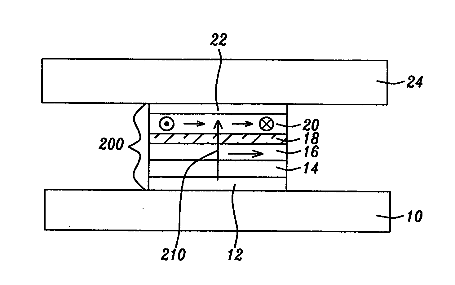
[0033]Referring next to FIG. 4, there is shown a second embodiment in which the layer configuration of the cell element (200) is formed as described in FIG. 1, but it is enclosed in a shield that closely surrounds the layers and protects them from extraneous fields and side-reading. The lower shield is formed first and is horizontally shaped as the lower shield in FIG. 1, but in forming the upper shield, two vertical layers (25) of magnetically permeable material, of width between approximately 5 and 500 angstroms, are formed projecting downward from a lower surface of a horizontal portion of the upper shield (24). The horizontal portion (24) is substantially of the same width and thickness as the lower shield (10), and are horizontally symmetrically disposed about the sides of the layer configuration but do not contact the sides. The spaces (15) between the upper and lower shields and the sides of the layer configuration are filled with an insulating material.

third embodiment

[0034]Referring to FIG. 5, there is shown a third embodiment in which the upper shield remains as in FIG. 4, but the lower shield (10) is formed to include a centrally symmetric pedestal (9), having substantially the same width as the cell element (200), on which the configuration of element layers is formed. The upper shield must be correspondingly raised and its downward projecting portions (25) must be lengthened. The pedestal raises the element within the region between the upper and lower shields, providing even greater protection of the element from extraneous external fields and side-reading.


PUM

PropertyMeasurementUnit
thicknessaaaaaaaaaa
thicknessaaaaaaaaaa
thicknessaaaaaaaaaa

Abstract

A CPP MTJ or GMR read sensor is provided in which the free layer is self-stabilized by a magnetization in a circumferential vortex configuration. This magnetization permits the pinned layer to be magnetized in a direction parallel to the ABS plane, which thereby makes the pinned layer directionally more stable as well. The lack of lateral horizontal bias layers or in-stack biasing allows the formation of closely configured shields, thereby providing protection against side-reading. The vortex magnetization is accomplished by first magnetizing the free layer in a uniform vertical field, then applying a vertical current while the field is still present.

Description

[0001]This is a Divisional Application of U.S. patent application Ser. No. 10 / 953,085, filed on Sep. 29, 2004, which is herein incorporated by reference in its entirety and assigned to a common assignee.BACKGROUND OF THE INVENTION[0002]1. Field of the Invention[0003]This invention relates generally to the fabrication of a giant magnetoresistive (GMR) or a tunneling magnetic junction (TMJ) magnetic field sensor in the current-perpendicular-to-plane (CPP) configuration, more specifically to self-stabilization provided by a vortex configuration of the magnetization of the free layer of such a sensor.[0004]2. Description of the Related Art[0005]The CPP (current perpendicular to plane) configuration of a giant magnetoresistive (GMR) sensor or tunneling magnetic junction (TMJ) sensor is a multi-layered configuration of magnetic and non-magnetic layers which includes a magnetically free layer, whose magnetic moment is free to respond to outside magnetic stimuli, separated by a non-magnetic...

Claims


Application Information

Patent Timeline
Patent Type & Authority Applications(United States)
IPC IPC(8): G11B5/33
CPCB82Y10/00B82Y25/00G01R33/093G11B5/3909Y10T29/49048G11B2005/3996G11C11/16Y10T29/49053Y10T29/49043G11B5/3912
Inventor MIN, TAIWANG, POKANGLI, MINVOGELI, OTTO
Owner HEADWAY TECH INC
Why Eureka
Try Eureka