Methods and systems for turning rotary components within rotary machines

a technology of rotary machines and components, applied in the field of rotary machines, can solve problems such as nacelles being damaged, nacelles being damaged, and degrading the operating performance of damaged nacelles

Active Publication Date: 2008-07-31
GENERAL ELECTRIC CO
View PDF1 Cites 57 Cited by
  • Summary
  • Abstract
  • Description
  • Claims
  • Application Information

AI Technical Summary

Benefits of technology

[0007]In another aspect, a turning gear control system is provided for rotating rotary components of a rotary machine including a brake disc. The turning gear control system includes a turning gear assembly that includes a gear plate, a pinion gear and a

Problems solved by technology

However, such nacelles may be damaged during transportation.
For example, such nacelles may be damaged during land transportation because the nacelles may be subjected to uneven terrain, turning corners, and / or other stress and / or shock / vibration inducing conditions experienced by known land transportation vehicles.
As a result, nacelle damage facilitates further damage and degrading operating performance of the damaged nacelles.
However, such nacelle components may be damaged during transportation and / or periods in which the nacelles are exposed to shock and vibration forces in a non-operating state.
More specifically, at least some nacelle components may experience false brinelling of drivetrain bearings and / or gears as a result of such vibration forces.
Therefore, in addition to the oil pump, the auxiliary device and systems used to turn the rotary nacelle components increase costs associated with transporting the nacelles.
Moreover, the periodic timing for turning the rotary nacelle components may not accurately distribute vibration forces throughout the bearings and / or gears and may increase the occurrence of false brinelling.

Method used


Image

  • Methods and systems for turning rotary components within rotary machines
  • Methods and systems for turning rotary components within rotary machines
  • Methods and systems for turning rotary components within rotary machines

Examples


Embodiment Construction

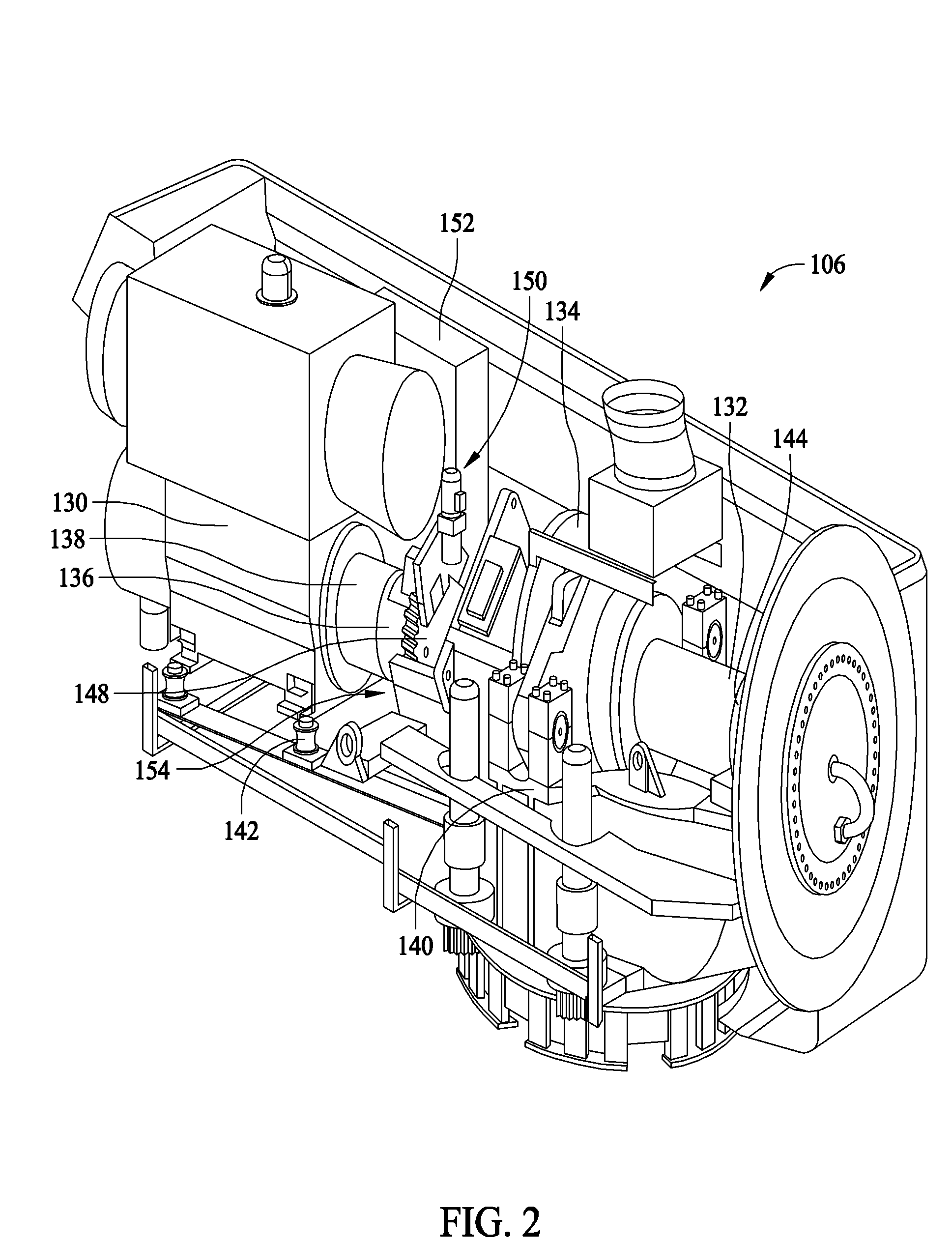
[0015]The exemplary methods and apparatus described herein overcome the disadvantages of at least some known wind turbine nacelle transportation methods and systems by providing methods and systems including a motion activated drivetrain turning gear assembly.

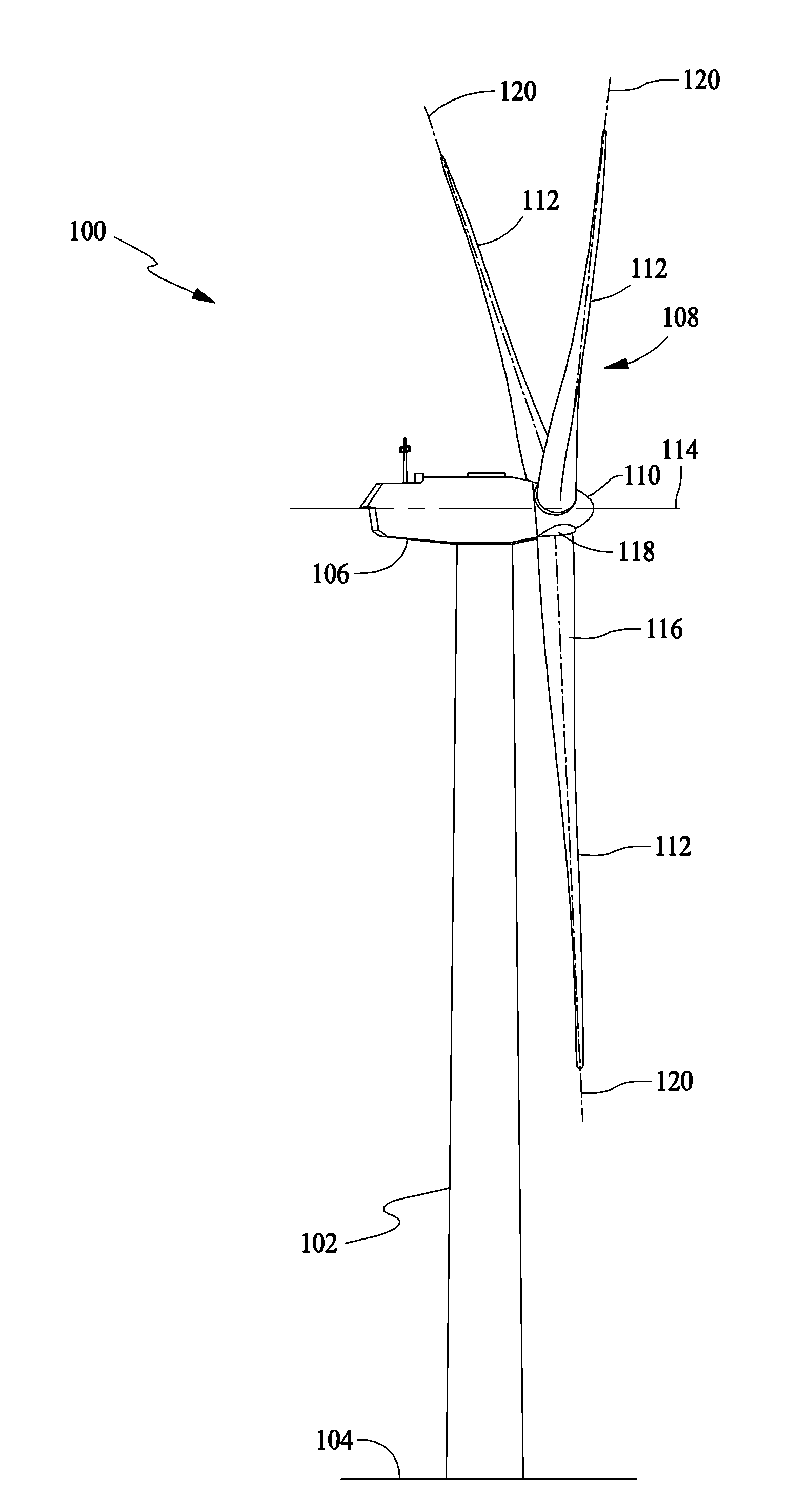
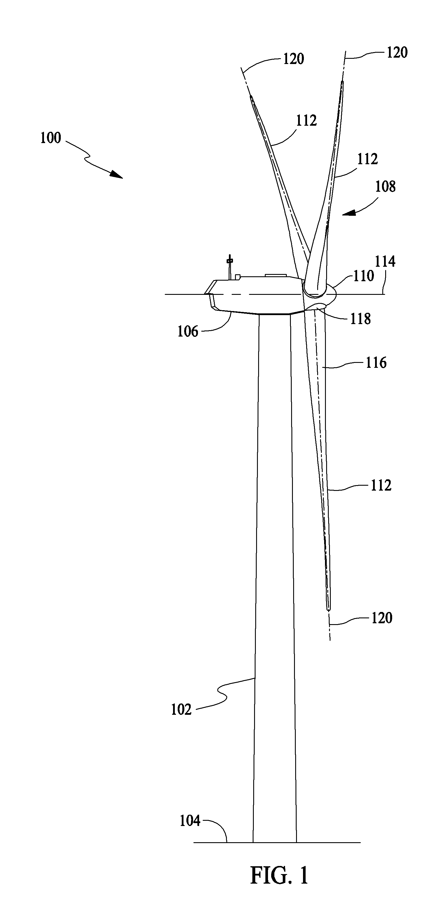
[0016]FIG. 1 is a schematic illustration of an exemplary wind turbine generator 100. In the exemplary embodiment, wind turbine 100 is a horizontal axis wind turbine. Alternatively, wind turbine 100 may be a vertical axis wind turbine. Wind turbine 100 includes a tower 102 erected on a supporting surface 104, a nacelle 106 coupled to tower 102, and a rotor 108 coupled to nacelle 106. Rotor 108 includes a rotatable hub 110 and a plurality of rotor blades (“blades”) 112 coupled to hub 110. In the exemplary embodiment, tower 102 is fabricated from tubular steel including a cavity (not shown) extending between supporting surface 104 and nacelle 106. In an alternative embodiment, tower 102 is a lattice tower. The height of tower 102 ...


PUM


Abstract

A method and apparatus of turning rotary components of a rotary machine having a brake disc includes providing a turning gear assembly. The turning gear assembly includes a gear plate, a pinion gear and a gear motor coupled to the pinion gear. The method also includes coupling the turning gear assembly within the rotary machine using the gear plate such that the pinion gear engages with the brake disc, detecting a motion of the rotary machine, and rotating the brake disc using the pinion gear based on the detected motion.

Description

BACKGROUND OF THE INVENTION[0001]This invention relates generally to rotary machines and more particularly, to methods and systems for turning rotary components within wind turbine nacelles.[0002]At least some known wind turbines are generally disassembled into four types of components such as, but not limited to, rotor blades, tower, rotor hubs, and nacelles for transportation. Some wind turbine components such as, but not limited to, the nacelles are substantially unitary precision instruments. As such, the nacelles are generally assembled at the manufacturer and remain intact during subsequent transportation.[0003]Generally, nacelles are stored in cargo containers and / or affixed to transport structures such as, but not limited to, railroad cars, trucks and / or ships for transportation to a storage site and / or an assembly site. Moreover, at least some known nacelles may be transported using more than one different mode of transportation, for example by rail, truck, and / or ship. How...

Claims


Application Information

Patent Timeline
IPC IPC(8): F04D27/00
CPCF03D7/0248F03D11/00F05B2250/40F05B2260/02F05B2260/4031Y10T477/343F05B2260/96Y02E10/722Y02E10/723Y10T74/19074F05B2260/902F03D80/00F03D15/10F03D9/25F03D9/11F03D80/70Y02E10/72
Inventor MOORE, BRADLEY GRAHAMHUDNALL, DAVID RAYMILLER, BRADELY
Owner GENERAL ELECTRIC CO
Why Eureka
Try Eureka