

Automotive-transmission clutch-pressure duration
a technology of clutch pressure and auto transmission, which is applied in the direction of clutches, gearing control, gearing elements, etc., can solve the problems of reducing the torque of the vehicle engine, on-coming clutch filling with hydraulic fluid more slowly, and side effects, so as to improve the ride comfort of passengers, reduce the shift shock, and improve the experience of shi
- Summary
- Abstract
- Description
- Claims
- Application Information
AI Technical Summary
Benefits of technology
Problems solved by technology
Method used
Image

Examples
Embodiment Construction
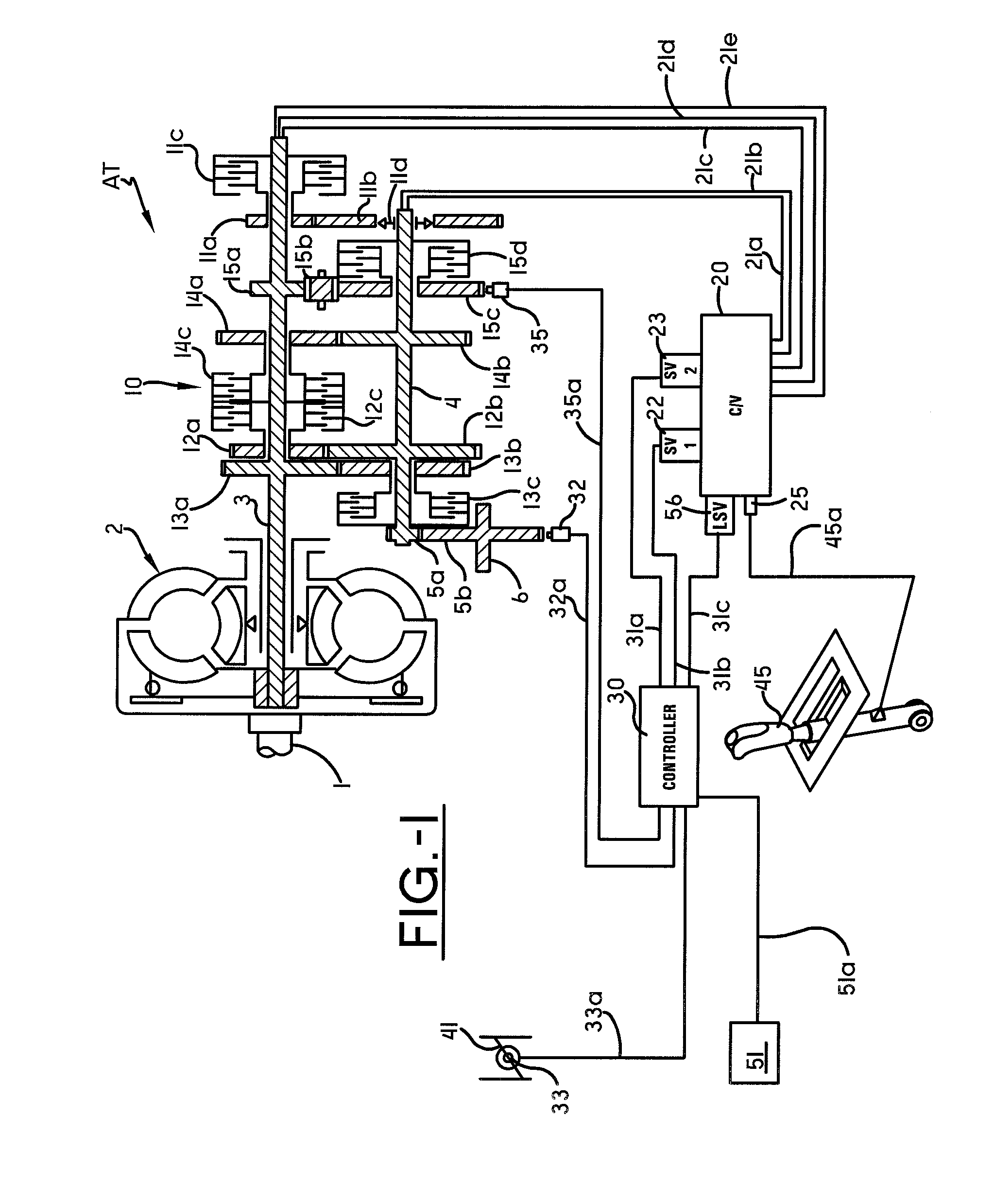
[0023]Referring now to the drawings wherein the showings are for purposes of illustrating embodiments of the invention only and not for purposes of limiting the same, a vehicle, not shown, may comprise a transmission system AT shown schematically in FIG. 1. The transmission system AT may have a transmission mechanism 10, a control system 30 (shown in more detail in FIG. 4) and a shift lever 45. The transmission mechanism 10 may comprise a plurality of gear trains for changing the speed of rotation of the engine-power-output transmitted from an engine output shaft 1 through a torque converter 2 and for applying the engine-power-output to an output shaft 6. The control system 30 may include a computer with software. Since, in this case, the type or configuration of the hardware or software and the range of features implemented can take various forms and ranges, virtual circuit blocks that implement those individual functions are used in the following description. The control system 30...
PUM
 Abstract
Description
Claims
Application Information