Acceleration shock reduction control system for vehicle

a control system and acceleration technology, applied in the direction of electric control, ignition automatic control, machines/engines, etc., can solve the problems of accelerating relatively slow for the throttle opening degree, requiring time for the backlash to be taken up, and the engine response seems slow in comparison

Active Publication Date: 2008-07-31
HONDA MOTOR CO LTD
View PDF20 Cites 9 Cited by
  • Summary
  • Abstract
  • Description
  • Claims
  • Application Information

AI Technical Summary

Benefits of technology

[0008]In this respect, an object of an embodiment of the present invention is to provide an acceleration shock reduction control system for a vehicle, in which the above-described problems associated with the conventional technique are eliminated, and which can reduce, without deteriorating the acceleration response, a shock at the time of accelerating the vehicle.
[0009]For solving the above-described problems, according to an embodiment of the present invention, an acceleration shock reduction control system for vehicle is provided. The acceleration shock reduction control system includes control means which determines a transition from a decelerating state to an accelerating state, and which thus controls the ignition of an internal combustion engine to adjust the output of the engine. In the acceleration shock reduction control system, upon detecting the transition from the decelerating state to the accelerating state, the control means gives an instruction for an ignition cut which is executed, after a predetermined waiting time period (Tw), over a predetermined time period (Tr, Tr′, Tr″) or a predetermined number of ignition cycles. According to an embodiment of the present invention, when the transition from the decelerating state to the accelerating state is detected, the ignition cut is executed after the predetermined waiting time period over the predetermined time period or the predetermined number of ignition cycles. Accordingly, it is possible to reduce the shock at the transition to the accelerating state by promptly reducing the engine speed after play existing in the drive system of the vehicle is taken up. As a result it is possible to reduce the shock at the transition to the accelerating state without deteriorating the acceleration response.
[0010]In the above-described configuration, it is preferable that the acceleration shock reduction control system further include a throttle opening degree sensor which detects a throttle opening degree, and that the transition from the decelerating state to the accelerating state be determined from an output of the throttle opening degree sensor. According to this configuration, the transition from the decelerating state to the accelerating state is determined from the output of the throttle opening degree sensor This makes it possible to detect the operation of the driver (rider) at an earlier stage, and also to apply the present invention to an existing configuration without making any modification thereon. As a result, an inexpensive acceleration shock reduction control system can be obtained.

Problems solved by technology

However, in the conventional configuration, since the ignition timing is retarded until backlash is taken up after the transition to an accelerating state, it requires time for the backlash to be taken up.
In addition, since the ignition timing is gradually returned to normal after the retarding, the acceleration is relatively slow for the throttle opening degree.
As a result, although the acceleration shock can be reduced, the engine response seems to be slow in comparison with a state where the above-described control is not performed.

Method used


Image

  • Acceleration shock reduction control system for vehicle
  • Acceleration shock reduction control system for vehicle
  • Acceleration shock reduction control system for vehicle

Examples


Embodiment Construction

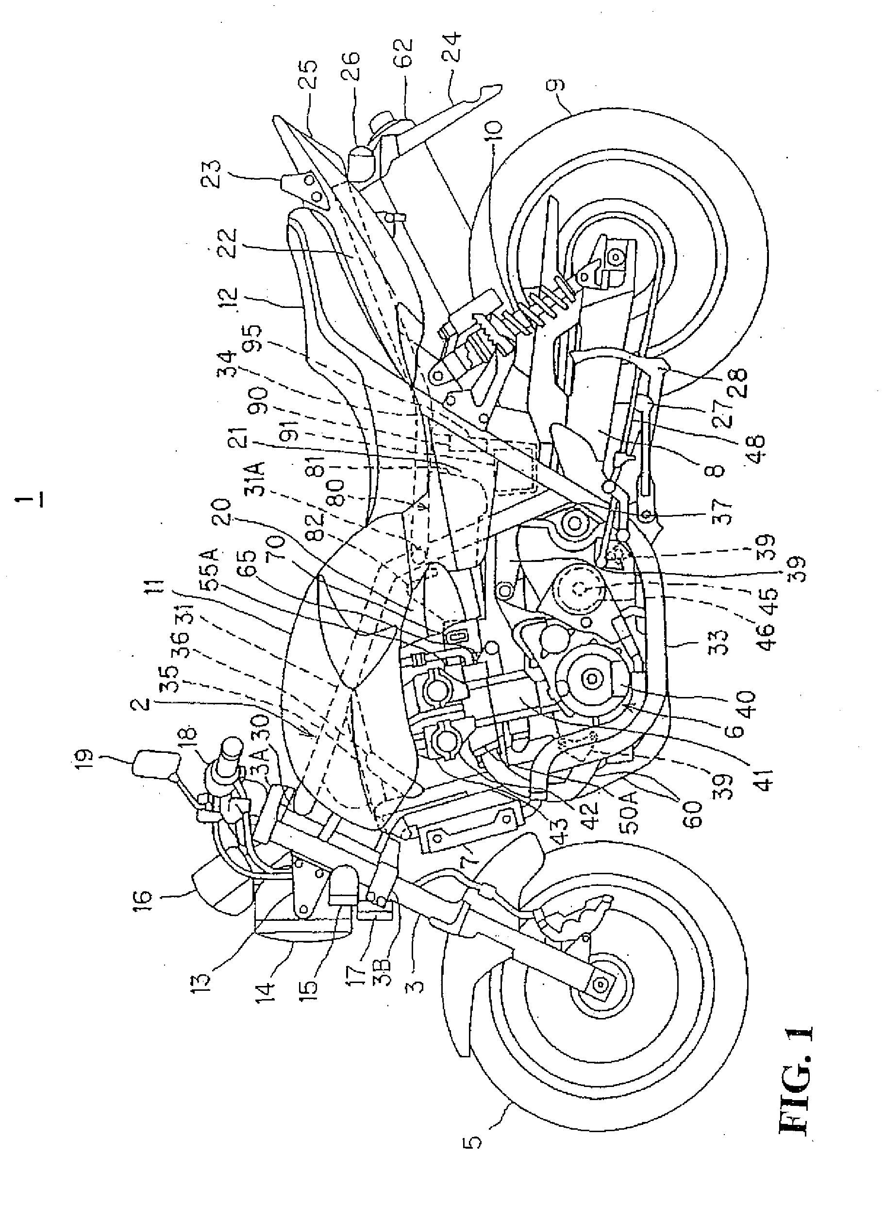
[0037]Hereinafter, descriptions will be given of embodiments of the present invention with reference to the attached drawings. Note that, in the descriptions, the front, rear, left, right, up, and down directions are of a vehicle body.

[0038]FIG. 1 is a side view showing an overall configuration of a motorcycle according to a first embodiment. The motorcycle 1 includes a vehicle body frame 2, a pair of left and right front forks 3, a steering handlebar 4, a front wheel 5, an engine (internal combustion engine) 6, a radiator 7, swing arms 8, a rear wheel 9, a pair of left and right rear cushions 10, a fuel tank 11, and a seat 12. The front forks 3 are rotatably supported by a head pipe 30 disposed on a front portion of the vehicle body frame 2. The handlebar 4 is attached to a top bridge 3A which supports the upper ends of the front forks 3. The front wheel 5 is rotatably supported by the front forks 3. The engine 6 is supported by the vehicle body frame 2 at substantially the center ...


PUM


Abstract

An acceleration shock reduction control system for a vehicle which can reduce a shock at a transition to an accelerating state without deteriorating an acceleration response. An acceleration shock reduction control system for vehicle includes a control unit which determines a transition from a decelerating state to an accelerating state, and which thus controls the ignition of an internal combustion engine to adjust the output of the engine. In the acceleration shock reduction control system, upon detecting the transition from the decelerating state to the accelerating state, the control unit gives an instruction for an ignition cut which is executed over a predetermined time period Tr after a predetermined waiting time period Tw elapses.

Description

CROSS-REFERENCE TO RELATED APPLICATIONS[0001]The present application claims priority under 35 USC 119 to Japanese Patent Application No. 2007-022335 filed on Jan. 31, 2007 the entire contents of which are hereby incorporated by reference.BACKGROUND OF THE INVENTION[0002][0003]1. Field of the Invention[0004]The present invention relates to an acceleration shock reduction control system for vehicle such as a motorcycle.[0005]2. Description of Background Art[0006]In general, in vehicles such as motorcycles, an acceleration shock often acts on the vehicle at the transition from a decelerating state to an accelerating state. This acceleration shock is caused by an event in which play existing in the drive system of the vehicle, that is, backlash is taken up. For the purpose of avoiding this acceleration shock, the following configuration has been conventionally proposed. More specifically, in this conventional configuration, shock due to backlash and the like at the transition from a dec...

Claims


Application Information

Patent Timeline
Patent Type & Authority Applications(United States)
IPC IPC(8): B60W10/06F02P5/15
CPCF02D41/045F02D41/107F02D41/126F02D2200/0404Y10T477/679F02D2250/28F02P5/1504F02P9/002Y10T477/67F02D2250/21
Inventor SATO, KATSUMIOKAWADA, NAOHISANIIMURA, RYUTA
Owner HONDA MOTOR CO LTD
Why Eureka
Try Eureka