
Novel device

a technology of a dispenser and a handle is applied in the field of dispenser devices, which can solve the problems of haphazard operation, risk of loss, damage or contamination of the product, and the complexity of the disclosed apparatus, and achieve the effect of convenient carrying around and cheap manufacturing

Inactive Publication Date: 2008-08-07
GLAXO GROUP LTD
View PDF60 Cites 0 Cited by
  • Summary
  • Abstract
  • Description
  • Claims
  • Application Information

AI Technical Summary

Benefits of technology

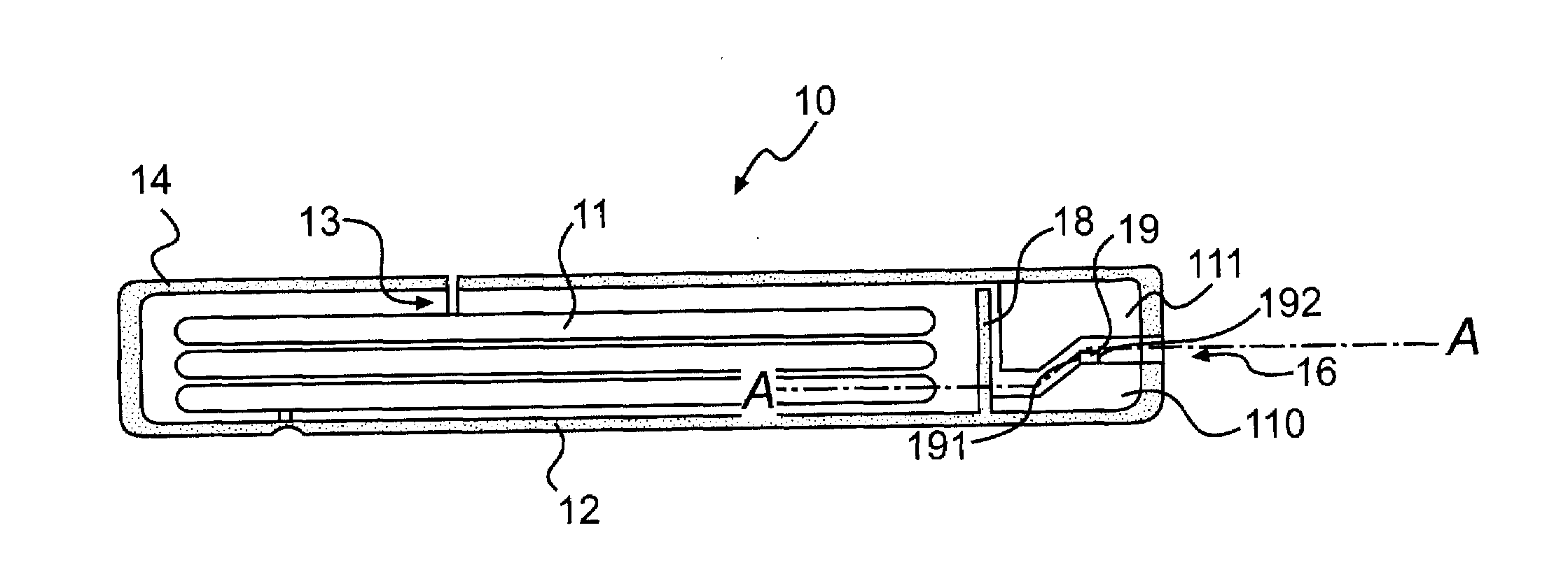
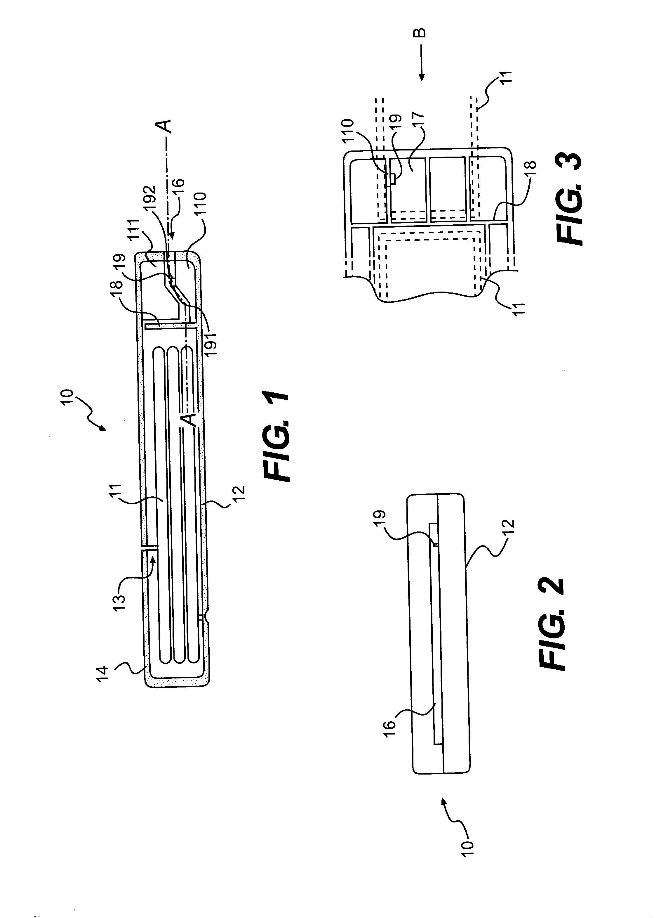
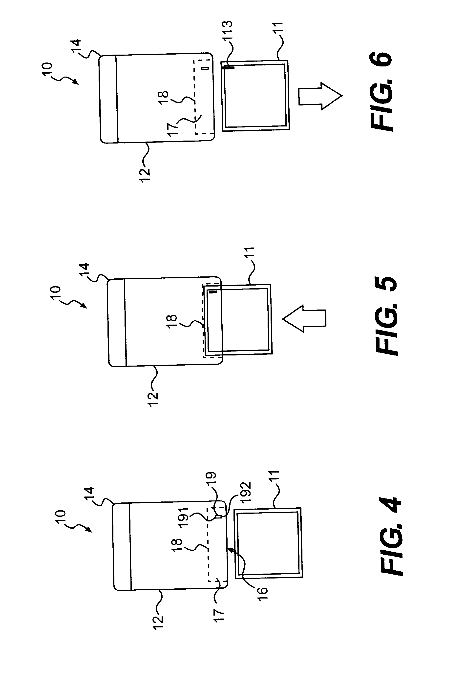
[0006]The slot opening preferably comprises an aperture in the outer surface of the container which approximates to the cross section of the sachet to be inserted through the slot opening. Typically in its cross section perpendicular to the insertion direction in which the sachet is to be inserted into the slot opening such an aperture is relatively long relative to its width. Such a slot opening can conveniently guide a sachet inserted therethrough and into the cavity towards and preferably into contact with the cutter. The slot and / or the cavity may incorporate guide means to further guide an inserted sachet towards and preferably into contact with the cutter. Such guide means may for example comprise internal ribs within the cavity which define a path for the sachet within the cavity.
[0018]In this second construction the abutment surface can limit the distance to which the sachet can be inserted into the cavity, i.e. the guide groove, and is suitably aligned so that the sachet may be passed through the guide groove in sliding contact with the abutment surface so that the abutment surface functions to guide the sachet. The cutter is positioned at a distance from the abutment surface so that the cutter cuts the sachet at a corresponding distance from the edge of the sachet which moves in sliding contact with the abutment surface.
[0024]In this third construction the abutment surface can function to limit the distance the sachet can be inserted into the cavity in the insertion direction, and the distance in the insertion direction between the cutter and the abutment surface can determine the corresponding distance from the edge of the sachet at which the sachet is cut.
[0031]Suitable relative positions of the slot opening, cavity and cutter can easily be determined empirically by those skilled in the art to cut any specific sachet at a suitable position and to a suitable extent.
[0034]By means of the dispenser of the invention sachets may be easily cut open without the risks encountered in tearing them open by hand. Sachets are typically generally rectangular (the term includes square) and in the dispenser of the invention the cutter may be so incorporated into the dispenser such that the sachet can be cut parallel to a straight edge of such a rectangular sachet.

Problems solved by technology

Although sachets are often provided with nicks or weakened areas at which they will preferentially tear, opening them can be a haphazard operation with the risk of loss, damage or contamination of the product.
The disclosed apparatus is a complex machine.

Method used


Image

  • Novel device
  • Novel device
  • Novel device

Examples


first embodiment

[0008]The cutter is located within the cavity and positioned such that a sachet extending into the cavity and the cutter may be brought into contact with each other to thereby cut the sachet. In this first embodiment the cutter may be configured and positioned within and relative to the cavity and the abutment in various constructions to cut the sachet in various alternative constructions.

[0009]In a first construction the cutter is positioned and aligned within the cavity such that the sachet may be brought into contact with the cutter by a movement of the sachet within the cavity in a first direction, and then brought out of contact with the cutter by a reciprocal movement of the sachet in an opposite second direction.

[0010]In this first construction the cutter may be arranged to cut the sachet either on the movement of the sachet in the first direction or in the second direction.

[0011]As sachets are typically flexible and liable to crumple under compression such an arrangement can...

second embodiment

[0025]In the invention a dispenser for sachets is provided comprising a container for containing a sachet and from which a sachet may be dispensed for use, the container body incorporating a cutter with which a sachet dispensed from the container may be brought into contact to thereby cut open the sachet, the dispenser being constructed to dispense a sachet along a dispensing path, and the cutter may be mounted to intercept a sachet traveling along this dispensing path to thereby cut open the sachet.

[0026]Such a dispensing path may be defined by a dispensing conduit along which the sachet is dispensed towards a dispensing outlet opening.

third embodiment

[0027]In this third embodiment the sachet may have a straight edge, e.g. it may be rectangular, and the direction of the dispensing path may be parallel to the straight edge direction of the sachet.

[0028]In use, a sachet may be dispensed from the container of this third embodiment along the dispensing path, and in the course of following the dispensing path the sachet is brought into contact with the cutter to thereby cut the sachet.

[0029]The cutter may comprise a sharp blade, e.g. made of metal or ceramic.

[0030]Preferably the cutter is shielded to prevent accidental contact with the user and consequent injury. This may be achieved for example by mounting the cutter deep within the cavity so that a user's fingers cannot be easily inserted through the slot opening to contact the cutter. This shielding is also achieved in forms of the dispenser of the invention in which the cutting edge of the cutter faces away from the insertion direction.

[0031]Suitable relative positions of the slot...


PUM

PropertyMeasurementUnit
distanceaaaaaaaaaa
widthaaaaaaaaaa
volumeaaaaaaaaaa

Abstract

A dispenser for sachets comprising a container for sachets, having a slot opening communicating with an internal cavity such that a sachet may be inserted into the slot into the cavity, with an abutment surface within the cavity to limit the distance the sachet may extend into the cavity, and a cutter located within the cavity to cut the sachet, preferably on a withdrawal movement so the sachet is in tension. In another embodiment the dispenser dispenses sachets along a dispensing path and a cutter is located in the dispensing path to intercept and cut the sachet.

Description

FIELD OF THE INVENTION[0001]This invention relates to a dispenser device, in particular to a dispenser device for the dispensing of products contained in sachets.BACKGROUND OF THE INVENTION[0002]Products are frequently provided in sachets. Sachets are well known articles, generally comprising two sheets of material joined at their edges to define an envelope volume between them. Sachets are typically made of thin plastics or metal, or metal-plastics material foil laminates. To obtain access to the product contained within the sachet, the sachet must be opened. This is normally achieved by the user tearing the sachet open by hand. Although sachets are often provided with nicks or weakened areas at which they will preferentially tear, opening them can be a haphazard operation with the risk of loss, damage or contamination of the product.[0003]U.S. Pat. No. 4,008,657 discloses an apparatus for dispensing a continuous strip of sachets and is provided with a moveable cutter which cuts th...

Claims


Application Information

Patent Timeline
Patent Type & Authority Applications(United States)
IPC IPC(8): B65H3/00G07F11/72
CPCB67B7/30G07F17/0092G07F11/72G07F11/66Y10T83/727Y10T83/8821Y10T83/889B65D83/08G07F11/68B65D25/52
Inventor ANDERSON, GREGOR JOHN MCLENNANKELLY, ANDREWRITCHIE, SIMONROBINSON, DAVID
Owner GLAXO GROUP LTD
Learn More