
Molding method, molded product and instrument panel

a technology of molded products and instruments, applied in the direction of manufacturing tools, roofs, vehicle sub-unit features, etc., can solve the problems of deterioration, gap generation, complex mechanism of die structure, etc., and achieve the effect of increasing manufacturing cost and deteriorating appearan

Inactive Publication Date: 2008-08-07
NIHON PLAST CO LTD
View PDF7 Cites 6 Cited by
  • Summary
  • Abstract
  • Description
  • Claims
  • Application Information

AI Technical Summary

Benefits of technology

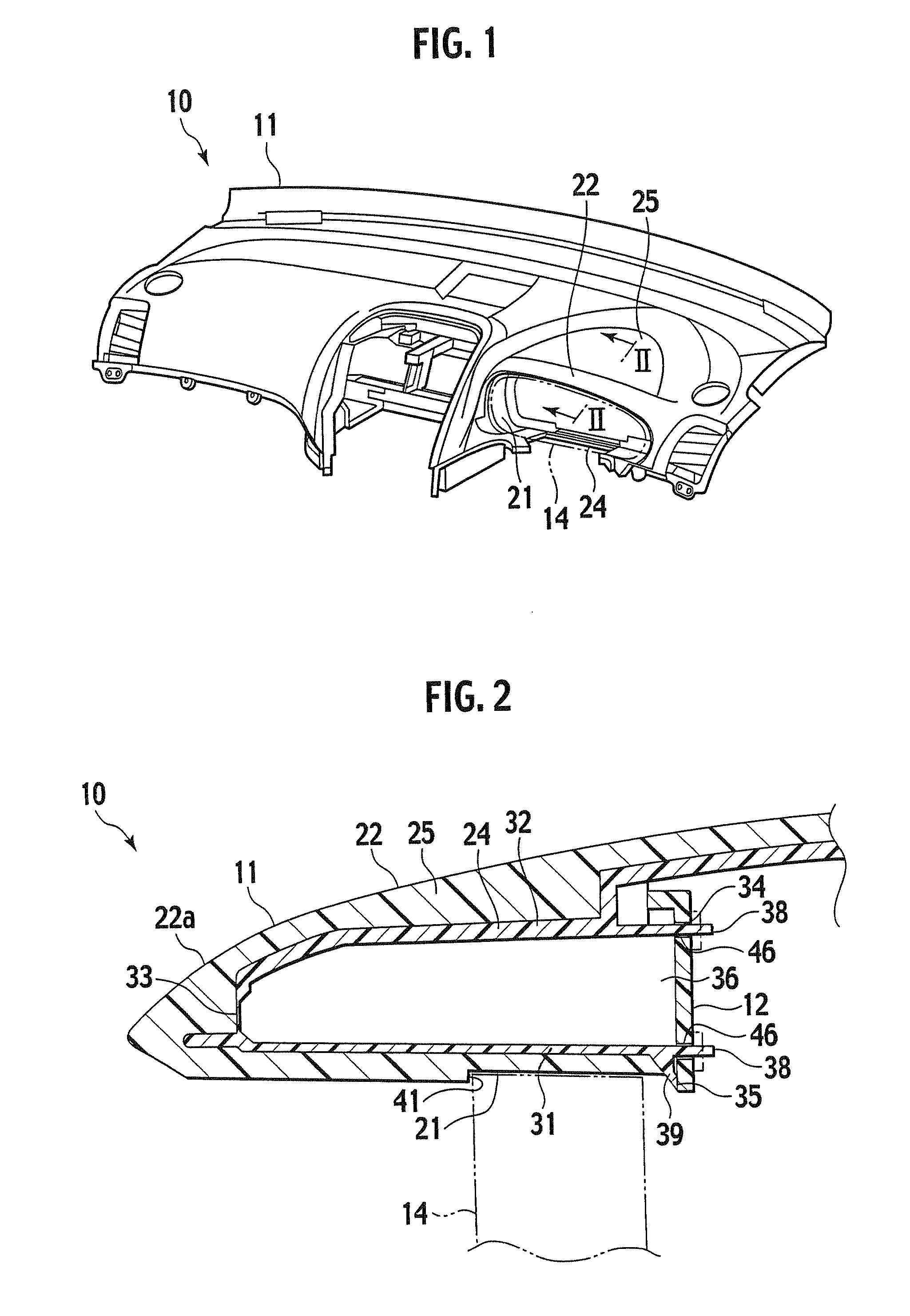
[0005]An instrument panel has a tubular opening and a component such as a meter is installed in the opening. However, a gap is generated if there is a dimensional error. As a result, its appearance is deteriorated. Accordingly, it can be considered to form a step at an installed portion of the component, but the step causes an “undercut”. In this case, since the die needs a slide core for the undercut, die structure needs a complex mechanism. As a result, manufacturing cost is increased.
[0006]It becomes possible to decrease the manufacturing cost if the outer layer and the base member are formed inside the die without using a preliminarily formed decorative sheet. However, a resin raw material of the outer layer may be transuded from a parting line of the slide core and a burr may be formed if the slide core is used for the undercut. As a result, the appearance is deteriorated. Therefore, removal processing of the burr is needed, and it is not easy to improve the appearance. Thus, the manufacturing cost increases after all.
[0007]An object of the present invention is to provide a molding method of a molded product capable of reducing manufacturing cost and easily improving its appearance, a molded product, and an instrument panel.

Problems solved by technology

However, a gap is generated if there is a dimensional error.
As a result, its appearance is deteriorated.
Accordingly, it can be considered to form a step at an installed portion of the component, but the step causes an “undercut”.
In this case, since the die needs a slide core for the undercut, die structure needs a complex mechanism.
As a result, manufacturing cost is increased.
As a result, the appearance is deteriorated.
Therefore, removal processing of the burr is needed, and it is not easy to improve the appearance.
Thus, the manufacturing cost increases after all.

Method used


Image

  • Molding method, molded product and instrument panel
  • Molding method, molded product and instrument panel
  • Molding method, molded product and instrument panel

Examples


Embodiment Construction

[0036]A molding method of a molded product, a molded product, and an instrument panel according to a first embodiment of the present invention will be described below with reference to the drawings.

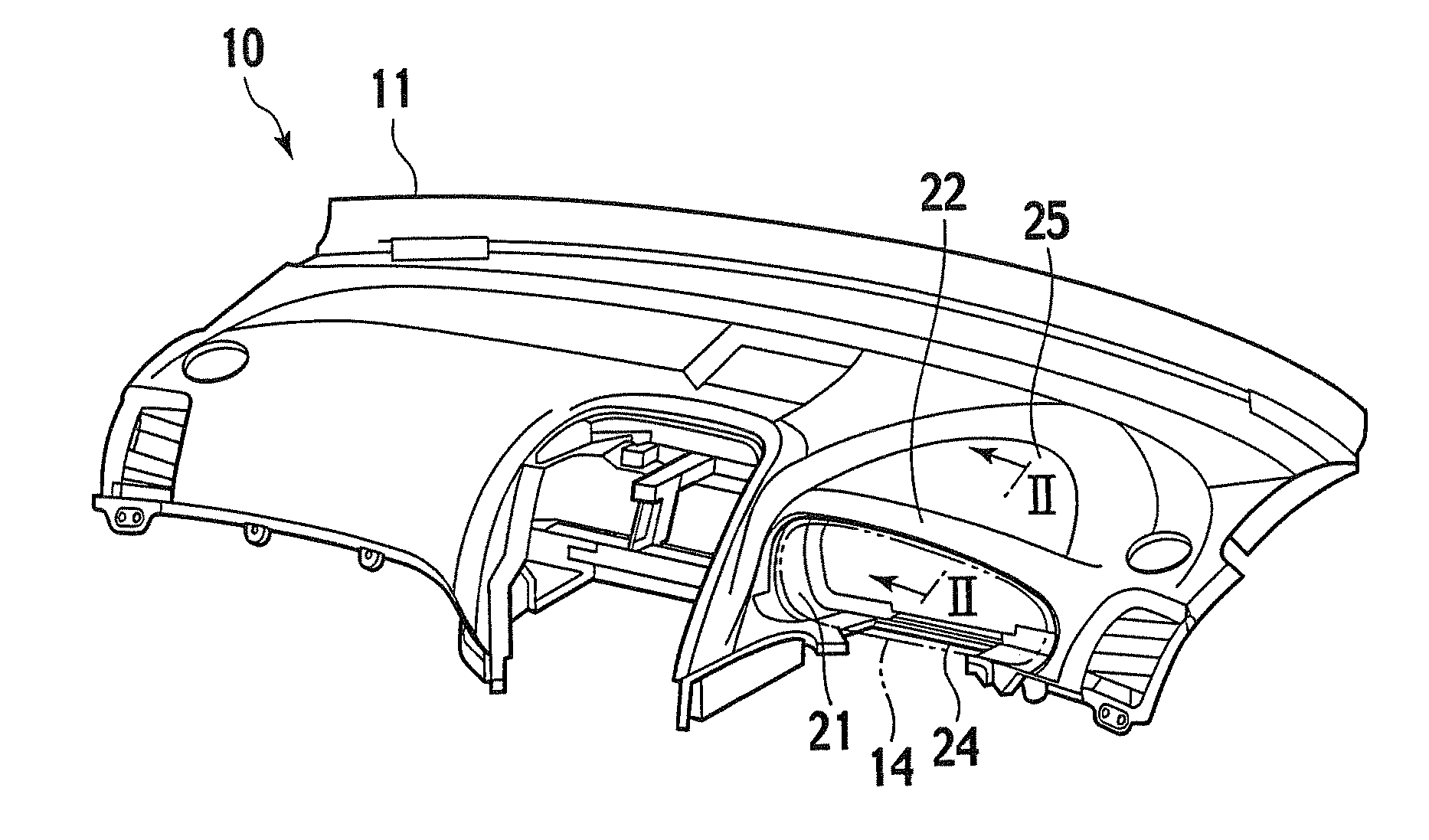
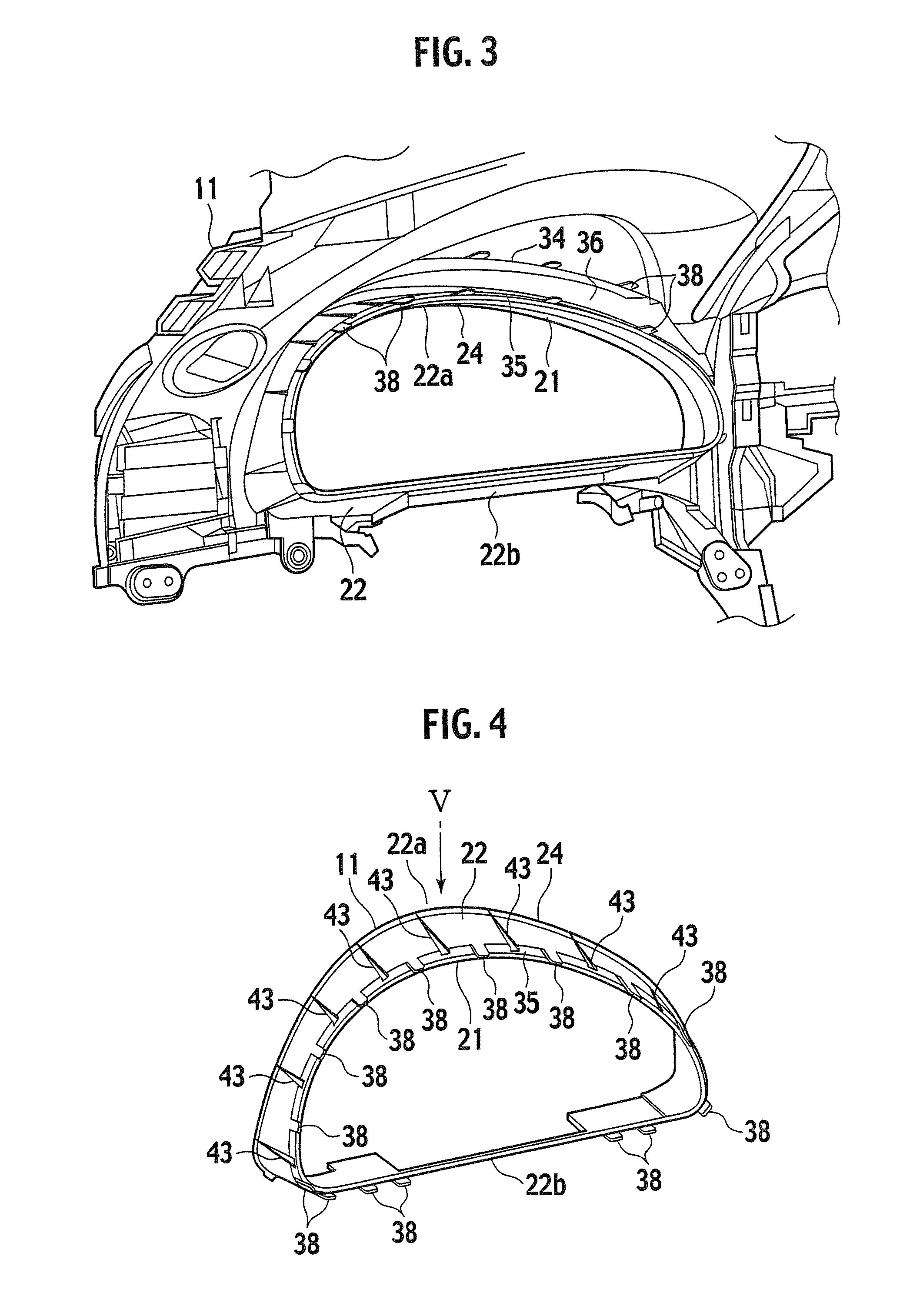
[0037]An instrument panel (molded product) 10 shown in FIG. 1 is installed with facing front seats in a compartment of an automobile (a vehicle). The instrument panel 10 is a vehicle interior component installed in a vehicle body with facing front-seat passengers. As shown in FIG. 1 to FIG. 7, the instrument panel 10 includes a panel body (molded product) 11 and a joint member 12 (FIGS. 2 and 8) installed onto the panel body 11. The instrument panel 10 further includes a meter assembly 14 (FIGS. 1 and 2), a ventilator (not shown), various switches (not shown), or the like, whereby an instrument panel assembly is configured.

[0038]A forward direction of the motor vehicle is used as a reference to describe directions such as above, below and both sides. Furthermore, with respect to the instr...


PUM

PropertyMeasurementUnit
areaaaaaaaaaaa
structureaaaaaaaaaa
rigidityaaaaaaaaaa

Abstract

An instrument panel includes a panel body and a joint member. The panel body includes a core member and an outer layer that covers the core member, and is formed by reaction injection molding. The panel body includes a meter installed portion. A recess of the meter installed portion becomes an undercut at the time of molding. A core member is provided with a deformable portion which is elastically deformable. The molded panel body can be demolded by deforming the deformable portion. There is no need to provide a slide core with a molding die. A deformation of the deformable portion is prevented by installing the joint member onto the demolded panel body. According to the instrument panel, it is possible to improve a product quality and reduce manufacturing cost.

Description

BACKGROUND OF THE INVENTION[0001]1. Field of the Invention[0002]The present invention relates to a molding method of a molded product (such as an automobile interior component) by die molding, a molded product, and an instrument panel.[0003]2. Description of the Related Art[0004]Conventionally, an instrument panel, which is installed with facing a front-seat passenger of a motor vehicle and made of a synthetic resin, is known. For example, the instrument panel is configured with a polypropylene base member and a decorative sheet disposed on the base member (for example, Japanese Patent Application Laid-open No. 2000-272377). The decorative sheet includes a foam layer made of polypropylene and a skin layer made of olefin or styrene elastomer. In this configuration, the decorative sheet is preliminarily inserted into a cavity of a die, and then a material of the base member is injected into the cavity to mold the instrument panel.SUMMARY OF THE INVENTION[0005]An instrument panel has a...

Claims


Application Information

Patent Timeline
Patent Type & Authority Applications(United States)
IPC IPC(8): B60K37/00B62D25/14B29C45/14B29C45/00
CPCB29C45/1676B29C45/4407B60Y2410/12B29L2031/3041B60K37/00B29L2031/3008
Inventor KAMANO, YOSHIFUMIMOCHIZUKI, HAJIMEYANAGIBASHI, SHINGOHAYAKAWA, NORIOCLARKE, ENDASEI, YASUNORI
Owner NIHON PLAST CO LTD
Learn More