
Phase locked loop and phase locking method

a phase locking and loop technology, applied in the direction of electrical equipment, pulse automatic control, etc., can solve the problems of difficult to reduce the size of the capacitor, difficult to reduce the size of the pll, and difficult to preserve the character of the pll, so as to reduce the operational range limit

Active Publication Date: 2008-08-07
SAMSUNG ELECTRONICS CO LTD
View PDF20 Cites 14 Cited by
  • Summary
  • Abstract
  • Description
  • Claims
  • Application Information

AI Technical Summary

Benefits of technology

The present invention provides a phase locking method and a phase locked loop (PLL) that can be insensitive to changes in process, voltage, and temperature variations. The method and PLL can generate a current proportional to the loop dynamic, which helps to reduce the impact of these variations. The PLL can be small in size, low in voltage, and can operate over a wide range of frequencies. The method and PLL can also be implemented in a low-voltage, low-current, and low-temperature environment. The PLL includes a charge pump, a voltage-current converter, and a current controlled oscillator, which can be implemented using MOS transistors. The method and PLL can be used in various applications such as communication devices, computer systems, and instrumentation.

Problems solved by technology

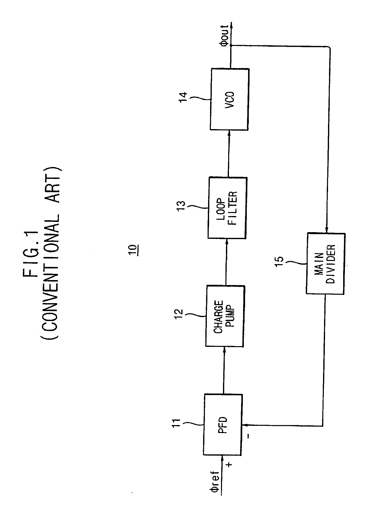
If the pump current provided from the charge pump is reduced to reduce the size of the capacitor in the loop filter, while maintaining the bandwidth of the PLL, the characteristics of the PLL actually become difficult to preserve.
In other words, reducing the size of the capacitor is not easy, and as a result, reducing the size of the PLL is difficult.

Method used


Image

  • Phase locked loop and phase locking method
  • Phase locked loop and phase locking method
  • Phase locked loop and phase locking method

Examples


Embodiment Construction

[0048]In the detailed illustrative embodiments disclosed herein, specific structural, and functional details are merely representative for purposes of describing aspects of the present invention. This invention can, however, be embodied in many alternate forms and should not be construed as limited to the embodiments set forth herein.

[0049]Accordingly, while the invention and embodiments are susceptible to various modifications and alternative forms, the specific embodiments herein are shown by way of example in the drawings and will herein be described in detail. It should be understood, however, that there is no intent to limit the invention to the particular embodiments disclosed herein, but on the contrary, the invention is to cover all modifications, equivalents, and alternatives falling within the spirit and scope of this disclosure and the claims.

[0050]It will be understood that, although the terms first, second, etc. can be used herein to describe various elements, these ele...


PUM


Abstract

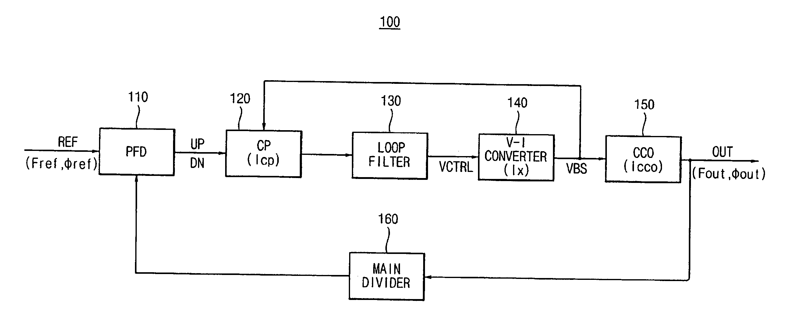
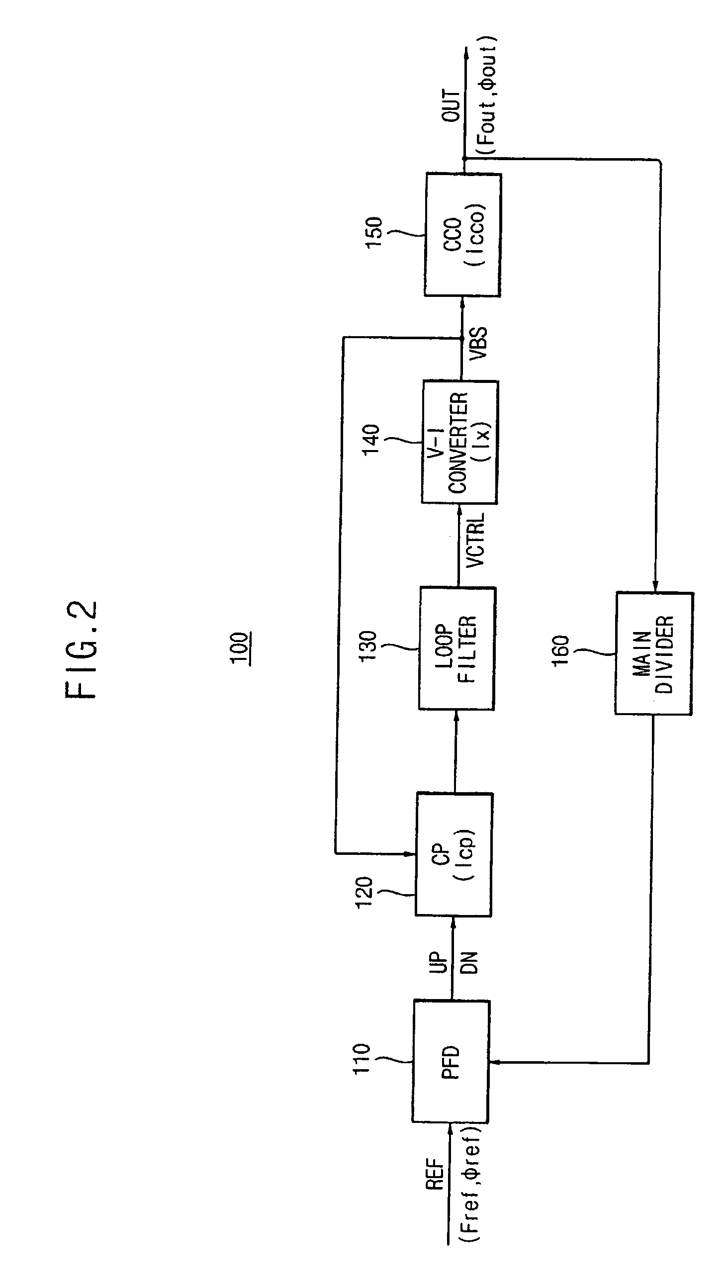
A phase locked loop includes a charge pump, a voltage-current converter, and a current controlled oscillator. The charge pump generates a pump current based on a bias voltage and a phase difference detection signal, in which the pump current is for adjusting a control voltage. The voltage-current converter is self-biased, generates the bias voltage, and converts the control voltage to a converter current. The current controlled oscillator generates an oscillator current based on the bias voltage, and generates an output signal that has a frequency corresponding to the oscillator current. The phase locked loop is insensitive to a division ratio and PVT variations.

Description

CROSS-REFERENCE TO RELATED APPLICATIONS[0001]This application is a continuation-in-part of U.S. patent application Ser. No. 11 / 646,101, filed on Dec. 27, 2006, now pending, which claims priority under 35 USC §119 to Korean Patent Application No. 10-2006-0002714, filed on Jan. 10, 2006 in the Korean Intellectual Property Office (KIPO), the disclosures of which are incorporated herein in their entirety by reference. This application also claims priority under 35 USC § 119 to Korean Patent Application No. 10-2007-0034328, filed on Apr. 6, 2007 in the KIPO, the disclosure of which is herein incorporated by reference in its entirety.BACKGROUND OF THE INVENTION[0002]1. Field of the Invention[0003]The present invention relates to apparatuses and methods for locking a phase of an output signal, and more particularly to a phase locking method and a phase locked loop (PLL) that includes a self-biased voltage-current converter.[0004]2. Description of the Related Art[0005]A phase locked loop (P...

Claims


Application Information

Patent Timeline
Patent Type & Authority Applications(United States)
IPC IPC(8): H03L7/085
CPCH03L7/0896H03L7/099H03L7/0898
Inventor JUNG, WOO-YOUNGKIM, YOUNG-MIN
Owner SAMSUNG ELECTRONICS CO LTD
Learn More