
Image processing method and image processing device

a processing method and image technology, applied in the field of image processing methods and image processing devices, can solve the problems of image becoming quite unnatural and one part of the image may not match, and achieve the effect of reducing the processing load

Inactive Publication Date: 2008-08-07
FUJITSU LTD
View PDF8 Cites 53 Cited by
  • Summary
  • Abstract
  • Description
  • Claims
  • Application Information

AI Technical Summary

Benefits of technology

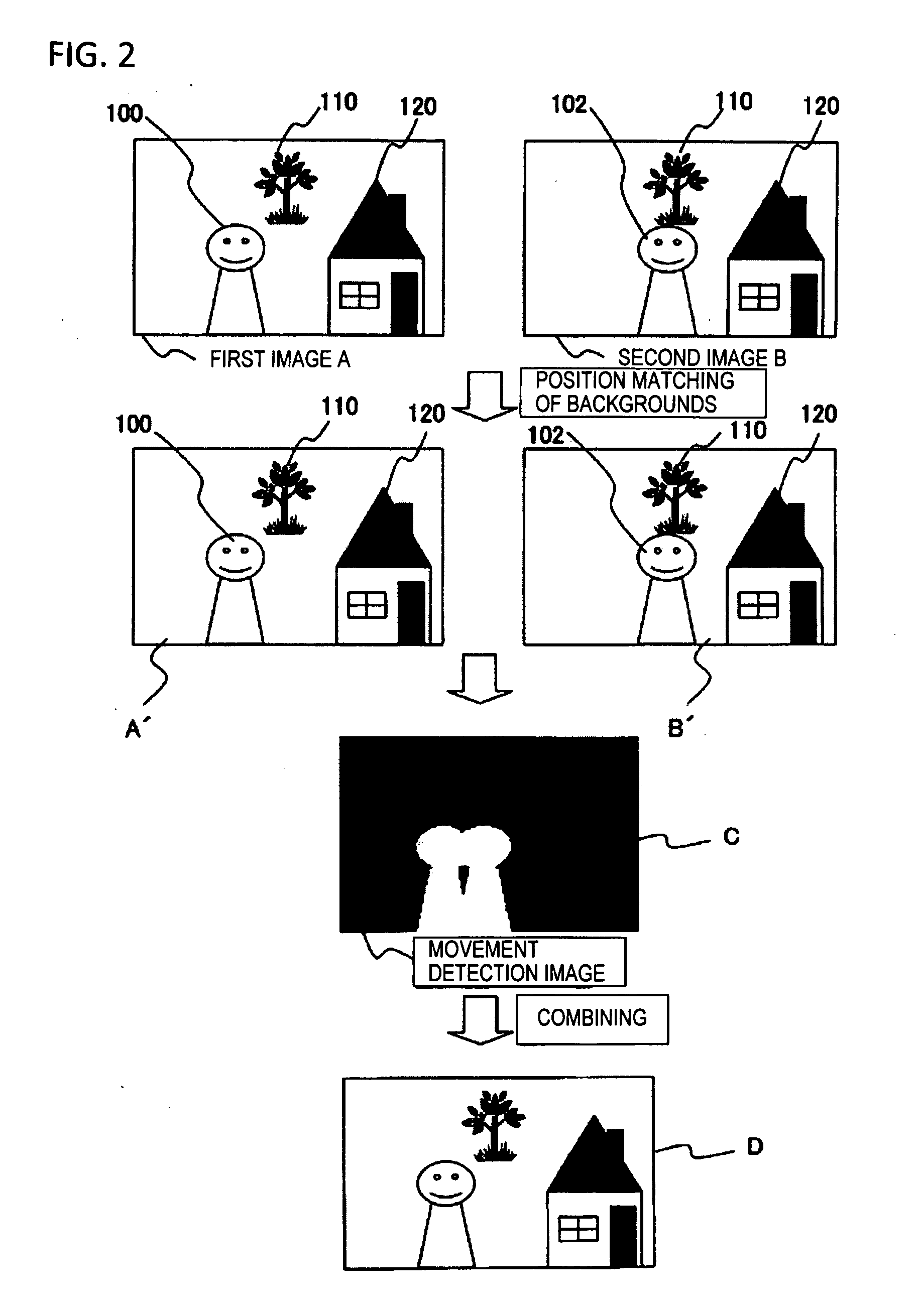
[0012]It is still another object of the present invention to provide an image processing method and an image processing device to acquire an image of an object that is not blurred, even if the object, other than a background, moves.
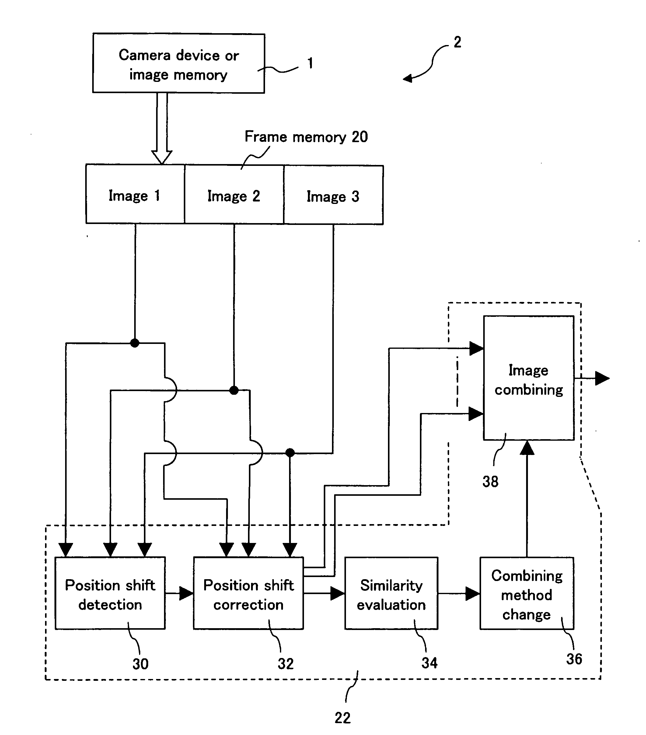
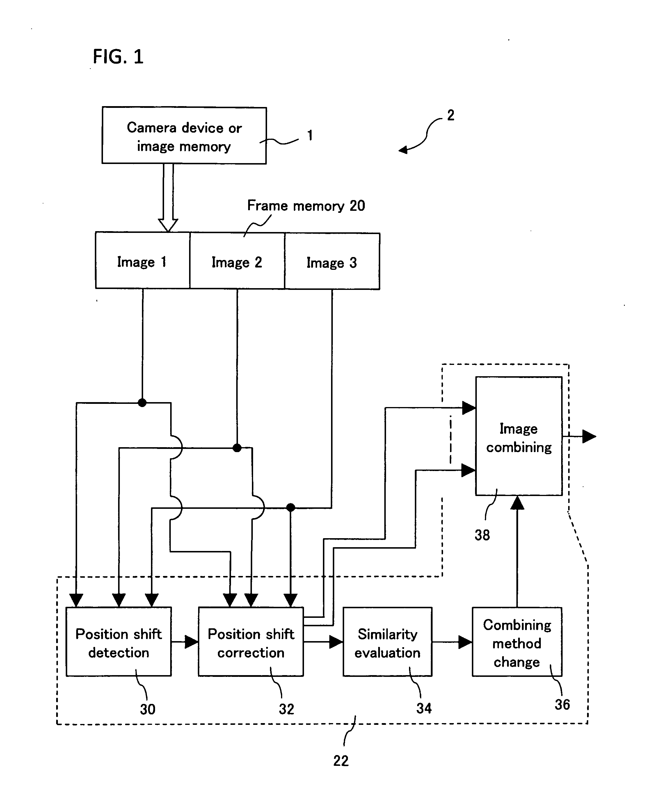
[0035]When a plurality of images are combined, a position shift between images is detected and corrected, and after the position shift is corrected the similarity of the images is evaluated, and the image combining method is changed according to the similarity, so it is possible to create an image having no position shift, due to the shaking of a camera, and object blurring, due to the movement of the object. Moreover, whether the images are combined or not is determined according to the similarity, so the processing load is reduced and an image having no object blurring can be created.

Problems solved by technology

In the case of the first prior art, however, the entire image is positioned with the position shift amount of the entire image, so if a shift amount of a part of the image is different from a shift amount of the other part of the image, the position of one part of the image may not match, even if the position of the other part of the image matches.
If the movement of the object is major, the image may become quite unnatural.

Method used


Image

  • Image processing method and image processing device
  • Image processing method and image processing device
  • Image processing method and image processing device

Examples


first embodiment

of Image Processing Method

[0087]FIG. 3 is a processing flow chart of a first embodiment of the image processing of the present invention, FIG. 4 is a flow chart depicting details of the similarity evaluation processing in FIG. 3, FIG. 5 is a graph depicting the level difference and edge intensity in FIG. 4, FIG. 6 is a diagram depicting the calculation of the edge intensity in FIG. 4, and FIG. 7 is a table showing the composing method in FIG. 3.

[0088]The image processing of the present embodiment will now be described with reference to FIG. 3.

[0089](S10) Images are shot by a digital camera. In this case, when a shutter is pressed once, the digital camera performs a plurality of short time exposure shooting, and acquires a plurality of consecutive images A and B.

[0090](S12) A processing unit 20 corrects the position shift of two images. Here the above mentioned KLT transform is used. According to the KLT transform, the characteristic points of two images are extracted and tracked to ...

second embodiment

of Image Processing Method

[0123]FIG. 14 is a processing flow chart of a second embodiment of the image processing of the present invention, and FIG. 15 is a diagram depicting the image processing method of FIG. 14.

[0124]The image processing of the present embodiment will now be described with reference to FIG. 14.

[0125](S60) Images are shot by a digital camera. In this case, when a shutter is pressed once, the digital camera performs a plurality of short time exposure shooting, and acquires a plurality of consecutive images A and B.

[0126](S62) A processing unit 20 corrects the position shift of two images. Here the above mentioned KLT transform is used. According to a KLT transform, the characteristic points of two images are extracted and tracked to detect a position shift, and the position shift is corrected. The position shift correction method, however, is not limited to this method.

[0127](S64) Then the processing unit 20 evaluates a similarity between images A′ and B′ for which...

third embodiment

of Image Processing Method

[0145]FIG. 20 is a processing flow chart of the third embodiment of the image processing method according to the present invention, FIG. 21 shows a table of increment values thereof, and FIG. 22 to FIG. 25 are diagrams depicting the operation thereof in FIG. 20. FIG. 20 is a processing flow chart of a variant form of the similarity evaluation step in FIG. 14 and FIG. 16.

[0146](S648) First a processing unit 20 initializes a high similarity counter for counting a number of pixels of which similarity is high, and a low similarity counter for counting a number of pixels of which similarity is low to “0”.

[0147](S650) The processing unit 20 calculates a level difference Δa of each pixel in a corresponding position of images 1 and 2 (images A and B). In the case of an RGB color image, for example, if the color image 1 is R1, G1 and B1, the color image 2 is R2, G2 and B2, and a pixel position is x, y, and the level difference Δa is calculated by the above mentioned...


PUM


Abstract

In a device for combining a plurality of images having a same photograph range, a position shift between the images having the same photograph range is detected, and the position shift of the images is corrected, and after the position shift is corrected, similarity of the respective portions between the images is evaluated, and the image combining method is changed according to the similarity evaluation. Therefore it is possible to create an image having no position shift due to the shaking of a camera and object blurring due to the movement of the object. Moreover, whether the images are combined or not is determined according to the similarity, hence the processing load is reduced and an image having no object blurring can be created.

Description

CROSS REFERENCE TO RELATED APPLICATIONS[0001]This application is a continuation of International Application No. PCT / JP2006 / 315121, filed on Jul. 31, 2006, now pending, herein incorporated by reference. Further, this application is based upon and claims the benefit of priority from the prior International Patent Application No. 2005 / 017147, filed on Sep. 16, 2005, the entire contents of which are incorporated herein by reference.TECHNICAL FIELD[0002]The present invention relates to an image processing method and image processing device for improving image quality by combining a plurality of images captured by an imaging device such as a digital camera, and more particularly to an image processing method and image processing device for improving image quality by combining images captured consecutively.BACKGROUND ART[0003]Along with the recent spread of digital image equipment, such as digital cameras, it is becoming possible to acquire images with excellent image quality by digital i...

Claims


Application Information

Patent Timeline
Patent Type & Authority Applications(United States)
IPC IPC(8): G06K9/40
CPCH04N1/3876H04N5/23248H04N5/23267H04N5/23277G06T2207/20212G06T5/003G06T5/50G06T2207/10144H04N5/272H04N23/6845H04N23/683H04N23/68G06T2207/20221G06T5/73
Inventor WATANABE, YURISHIMIZU, MASAYOSHIMURASHITA, KIMITAKAMIYAKAWA, AYUCHUJO, KAORUWAKAMATSU, TAKASHI
Owner FUJITSU LTD
Learn More