Transmission system and transmission apparatus

Inactive Publication Date: 2008-08-07
FUJITSU LTD
View PDF1 Cites 20 Cited by
  • Summary
  • Abstract
  • Description
  • Claims
  • Application Information

AI Technical Summary

Benefits of technology

[0017]In a transmission system of the present invention, in a case in which a termination unit that can receive a low-speed signal receives a high-speed signal and a reception processing part enters a free running state; in order to recover clock synchronization from the clock free running state of the termination unit, the terminal apparatus generates a low-bit-rate recovery signal, mult

Problems solved by technology

Accordingly, in the PON system of the related art, it is difficult to perform communication by using differing transmission bit rates.
Accordingly, if, after that, the ONU receives low-speed data, clock synchronization becomes unstable.
Since, in reception processing performed on the data 6-5, data reproduction is

Method used


Image

  • Transmission system and transmission apparatus
  • Transmission system and transmission apparatus
  • Transmission system and transmission apparatus

Examples


Embodiment Construction

[0025]An embodiment of the present invention is described below with reference to the accompanying drawings.

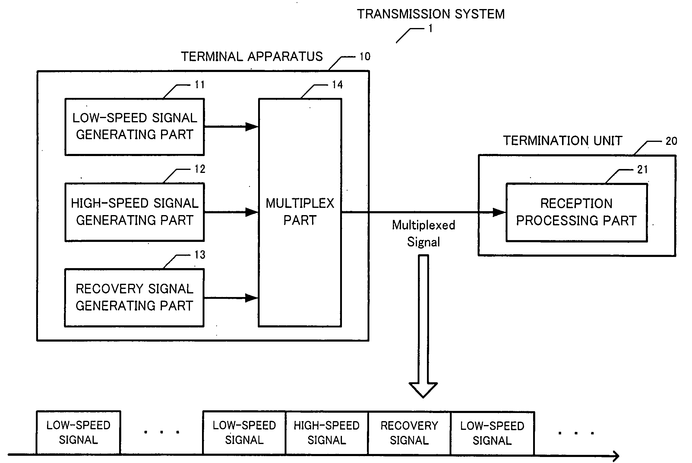
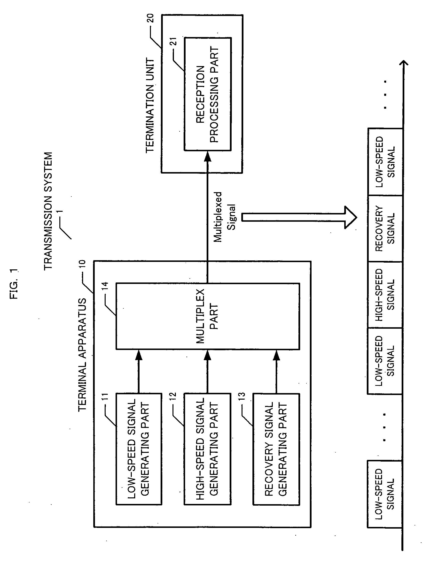
[0026]FIG. 1 is a block diagram showing the principle of a transmission system 1. The transmission system 1 includes a terminal apparatus 10 and a termination unit 20. The terminal apparatus 10 includes a low-speed signal generating part 11, a high-speed signal generating part 12, a recovery signal generating part 13, and a multiplex part 14. The termination unit 20 includes a reception processing part 21.

[0027]The low-speed signal generating part 11 generates a low-speed signal having a low bit rate. The high-speed signal generating part 12 generates a high-speed signal having a high bit rate. When the reception processing part 21 enters a free running state in response to receiving a high-speed signal, the recovery signal generating part 13 generates a low-bit-rate recovery signal for recovering clock synchronization from the free running state.

[0028]The multiplex part 14 ge...


PUM


Abstract

On an optical access network, transmission at different bit rates is realized without modifying subscriber units. A low-speed signal generating part generates a low-speed signal having a low bit rate. A high-speed signal generating part generates a high-speed signal having a high bit rate. A recovery signal generating part generates a recovery signal. A multiplex part generates and sends a multiplexed signal obtained by multiplexing the low-speed signal, the high-speed signal, and the recovery signal. A reception processing part performs processing for receiving the multiplexed signal by extracting clocks from the low-bit-rate signal. When the reception processing part enters a free running state in response to receiving the high-speed signal, the recovery signal generating part generates the recovery signal at a low bit rate in order to recover clock synchronization from the free running state.

Description

BACKGROUND OF THE INVENTION[0001]1. Field of the Invention[0002]The present invention relates to transmission systems and a transmission apparatus, and in particular, to a transmission system and a transmission apparatus for transmitting a signal on an optical access network.[0003]2. Description of the Related Art[0004]In recent years, with widespread use of the Internet, information communication networks have become widely used in homes and companies. Regarding optical access networks, a PON (passive optical network) has come to be widely employed as an optical access system in order to provide a higher-speed, large-capacity service.[0005]FIG. 6 is a block diagram showing the configuration of a PON system 5. The PON system 5 includes an OLT (optical line terminal) 51 provided in a station, a star coupler 52 for performing optical demultiplication and multiplication, and ONUs (optical network units) 53-1 to 53-n provided for subscribers.[0006]The OLT 51 is connected to the ONUs 53-...

Claims


Application Information

Patent Timeline
IPC IPC(8): H04J3/00H04L12/44
CPCH04J3/0605H04J3/1694H04Q2011/0045H04L7/0083H04Q11/0067H04J3/22
Inventor YAMABANA, TETSUJI
Owner FUJITSU LTD
Why Eureka
Try Eureka