
Configurable shader ALU units

a shader and alu unit technology, applied in the field of graphics data processing methods and apparatuses, can solve the problems of defective arithmetic logic units within the group that includes the first arithmetic logic unit, and achieve the effect of reducing the power consumption of the shader unit and increasing the dynamically changing amount of alu processing bandwidth

Active Publication Date: 2008-08-07
ATI TECH INC +1
View PDF65 Cites 21 Cited by
  • Summary
  • Abstract
  • Description
  • Claims
  • Application Information

AI Technical Summary

Benefits of technology

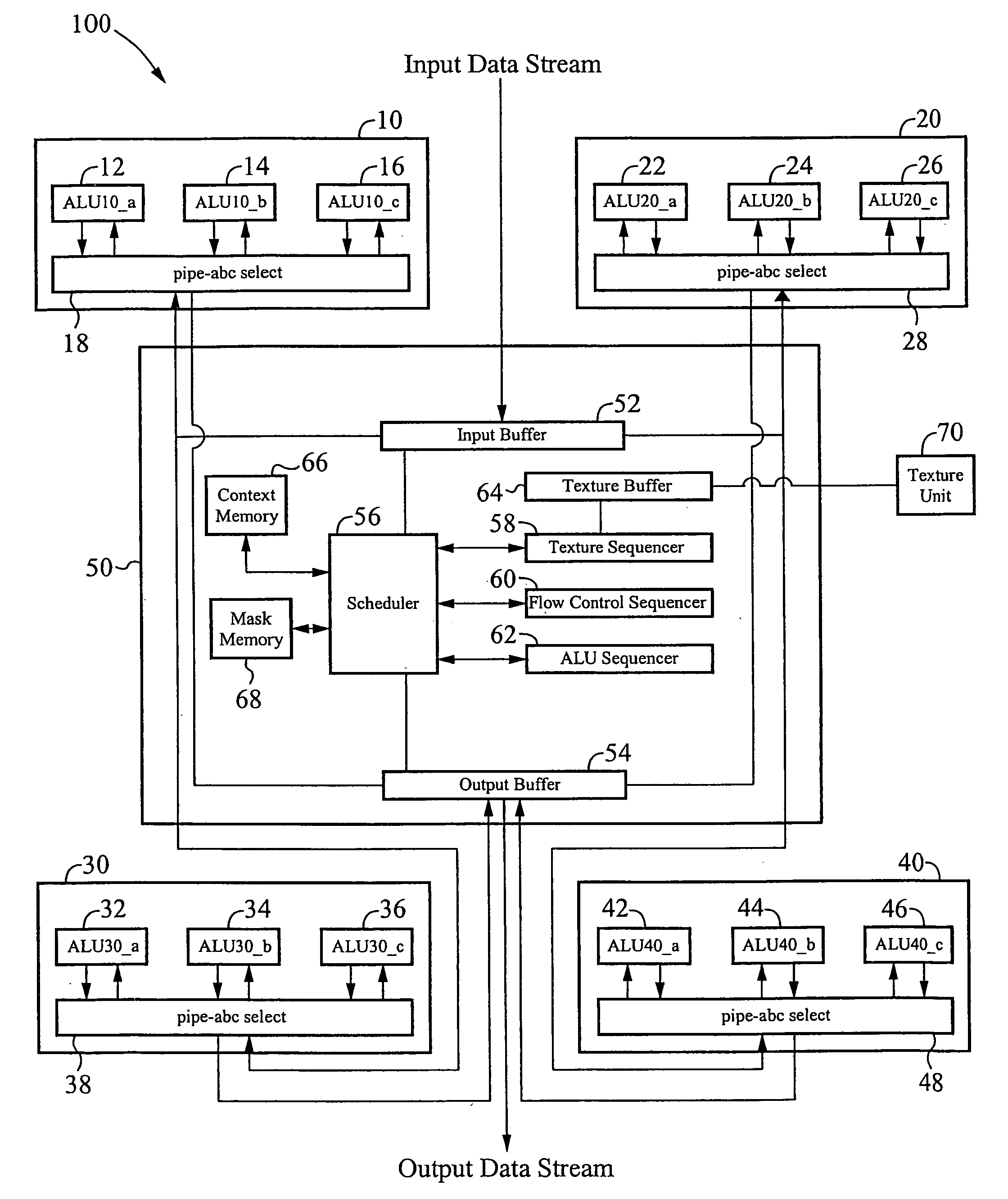
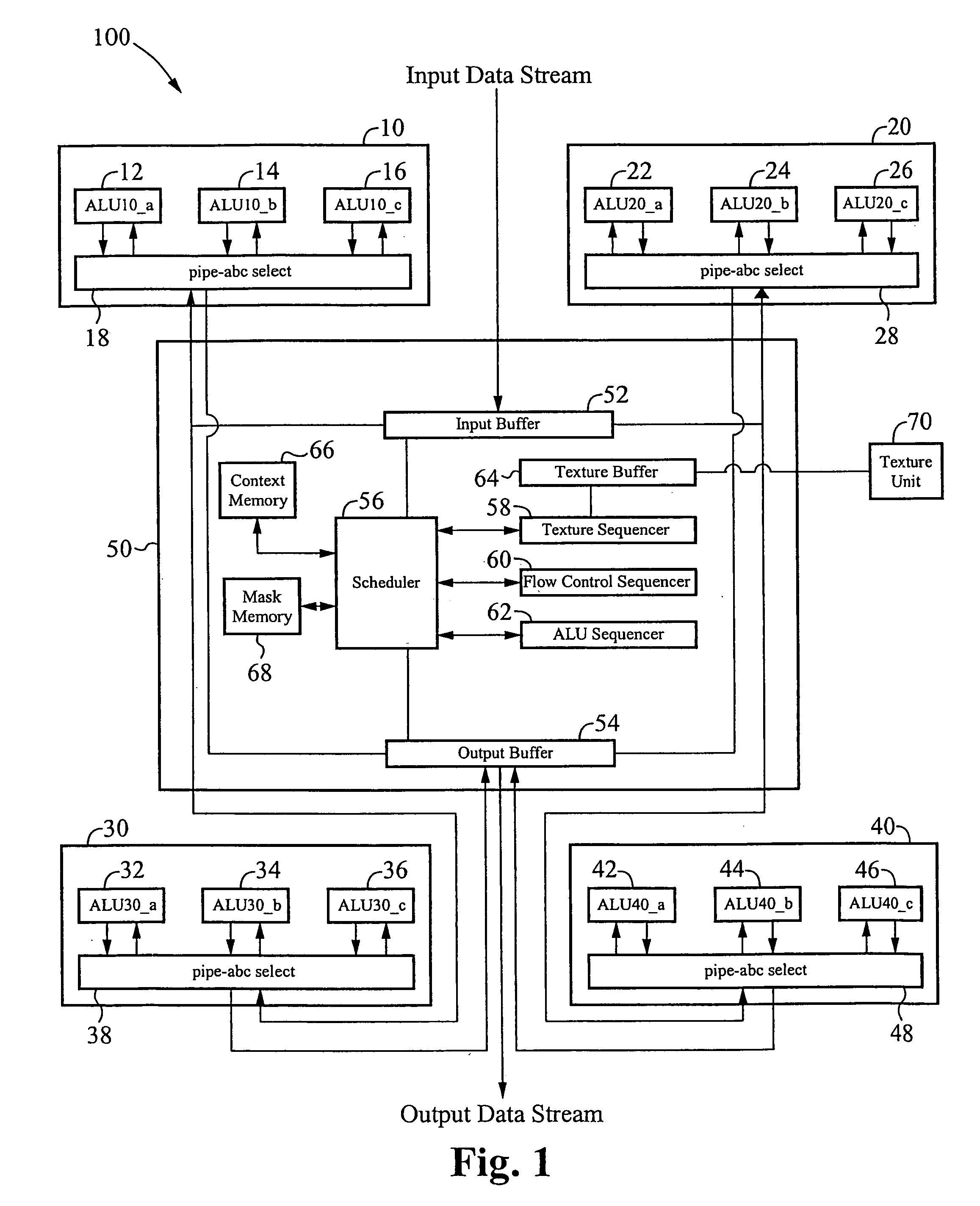
[0005]A shader unit is configured to provide an increased and dynamically changeable amount of ALU processing bandwidth. The shader unit includes a plurality of ALUs for processing pixel data according to a shader program. Each of the ALUs is preferably configurable to be enabled and disabled. When disabled, the ALU is powered off, thereby reducing the power consumption of the shader unit. In one embodiment, the plurality of ALUs are logically configured into groups called ALU-pipes, each of which can be enabled and disabled. When an ALU-pipe is disabled, each ALU associated with the disabled ALU-pipe is disabled. The shader unit includes a sequencer that executes the shader program, determines the number of ALUs to be enabled, receives an input data stream of pixel data, assigns groups of pixel data to each enabled ALU, sends the assigned pixel data to their respective ALUs, and sends ALU instructions to the ALUs to process the received pixel data according to the shader program.
[0007]In another aspect of the present invention, a shader unit includes a sequencer to provide control instructions, and a plurality of processing integrated circuit chips coupled to the sequencer, each integrated circuit chip includes a plurality of arithmetic logic units, wherein each processing integrated circuit chip includes at least one defective arithmetic logic unit, further wherein each of the plurality of arithmetic logic units is dynamically configurable to be enabled or disabled according to the control instructions provided by the sequencer, thereby increasing a yield for processing integrated circuit chips. The sequencer can dynamically configure a number of enabled arithmetic logic units. Each processing integrated circuit chip preferably includes a same number of defective arithmetic logic units, and each processing integrated circuit chip includes a same number of arithmetic logic units. The arithmetic logic units within the shader unit can be logically configured into a plurality of groups, wherein each group includes one arithmetic logic unit from each processing integrated circuit chip. When a first arithmetic logic unit on a first processing integrated circuit chip is defective, then each arithmetic logic unit within the group that includes the first arithmetic logic unit is also defective. The arithmetic logic units included within a group comprising defective arithmetic logic units are disabled and powered off. Each group can be coupled to a clock enable circuit. The arithmetic logic units within a first logical group can be powered off by disabling a corresponding first clock enable circuit. The sequencer includes an input buffer to receive an input stream of pixel data and a scheduler to direct a block of the received pixel data to each enabled arithmetic logic unit. The sequencer also includes an arithmetic logic unit sequencer that generates an arithmetic logic unit instruction, wherein the arithmetic logic unit sequencer sends the arithmetic logic unit instruction to each enabled arithmetic logic unit in response to a control instruction sent by the scheduler.

Problems solved by technology

When a first arithmetic logic unit on a first processing integrated circuit chip is defective, then each arithmetic logic unit within the group that includes the first arithmetic logic unit is also defective.

Method used


Image

  • Configurable shader ALU units
  • Configurable shader ALU units
  • Configurable shader ALU units

Examples


Embodiment Construction

[0012]Embodiments of a shader unit are directed to a dynamically configurable apparatus that processes a selectable and programmable number of pixels per clock cycle. Using the dynamically configurable shader unit, one ALU instruction is executed for a selectable number of pixels per clock cycle.

[0013]FIG. 1 illustrates one embodiment of a configurable shader unit 100. The shader unit 100 includes processing units 10, 20, 30, and 40, a sequencer 50, and a texture unit 70. The sequencer 50 includes an input buffer 52, an output buffer 54, a scheduler 56, a texture sequencer 58, a flow control sequencer 60, an ALU sequencer 62, a texture buffer 64, a context memory 66, and a mask memory 68. The shader unit 100 is configured to receive an input data stream, where the data stream includes a series of pixel data. Alternatively, the input data stream can be of any conventional data type. The shader unit 100 performs mathematical operations to manipulate the received pixel data, and output...


PUM


Abstract

A shader unit is configured to provide an increased and dynamically changeable amount of ALU processing bandwidth. The shader unit includes a plurality of ALUs for processing pixel data according to a shader program. Each of the ALUs is configurable to be enabled and disabled. When disabled, the ALU is powered off, thereby reducing the power consumption of the shader unit. In one embodiment, the plurality of ALUs are logically configured into groups called ALU-pipes, each of which can be enabled and disabled. When an ALU-pipe is disabled, each ALU associated with the disabled ALU-pipe is disabled. The shader unit includes a sequencer that executes the shader program, determines the number of ALUs to be enabled, receives an input data stream of pixel data, assigns groups of pixel data to each enabled ALU, sends the assigned pixel data to their respective ALUs, and sends ALU instructions to the ALUs to process the received pixel data according to the shader program.

Description

RELATED APPLICATIONS[0001]This application claims benefit of priority under 35 U.S.C. section 119(e) of co-pending U.S. Provisional Patent Application 60 / 880,806 filed Jan. 16, 2007, and entitled “Configurable Shader ALU Units”, which is incorporated herein by reference.FIELD OF THE INVENTION[0002]The present invention relates to a method of and an apparatus for processing graphics data. In particular, the present invention relates to a method of and apparatus for processing graphics data using configurable shader arithmetic logic units.BACKGROUND OF THE INVENTION[0003]In graphics processing, data is grouped as pixels, which are processed according to a series of processing instructions referred to as shader instructions. Each shader instruction defines a mathematical operation to be performed on the pixel. By applying a shader instruction to a pixel, the pixel value is changed according to the mathematical operation defined by the shader instruction. Application software defines th...

Claims


Application Information

Patent Timeline
Patent Type & Authority Applications(United States)
IPC IPC(8): G06F9/302
CPCG06F9/3001G06T1/20G06F9/3897
Inventor POON, ELAINEXU, XIAOLING SHERRY
Owner ATI TECH INC
Learn More