Inserts for engine exhaust systems

a technology of exhaust system and insert, which is applied in the direction of machines/engines, instruments, transportation and packaging, etc., can solve the problems of not necessarily the case, the noise level is certainly not acceptable in most operating environments, and the modified exhaust system may produce a sound level, so as to reduce the exhaust sound emissions of the engine exhaus

Inactive Publication Date: 2008-08-14
BALLARD EBBIN C
View PDF99 Cites 6 Cited by
  • Summary
  • Abstract
  • Description
  • Claims
  • Application Information

AI Technical Summary

Benefits of technology

[0011]Each of the various embodiments may be installed within an existing open exhaust pipe, i.e., one not having any internal sound reducing structure therein, by sliding the attachment or support ring into the interior of the pipe and using a flexible tool to work the insert into the pipe to the location desired. The flexibility of the conical mesh portion allows the insert to bend and flex to pass through curved or bent areas of the exhaust pipe without jamming therein. Any practicable number of such inserts, in any practicable configuration, may be installed wit

Problems solved by technology

While virtually all automobiles and trucks come equipped at the time of purchase with adequate sound suppression systems for their engines, this is not necessarily the case with many vehicles intended for off-road use.
While this may be acceptable in some circumstances, the resulting noise level is certainly not acceptable in most operating environments.
One problem with such modification is that the resulting modified exhaust system may produce a sound level that exceeds the maximum permitted by law for the jurisdiction and/or typ

Method used


Image

  • Inserts for engine exhaust systems
  • Inserts for engine exhaust systems
  • Inserts for engine exhaust systems

Examples


first embodiment

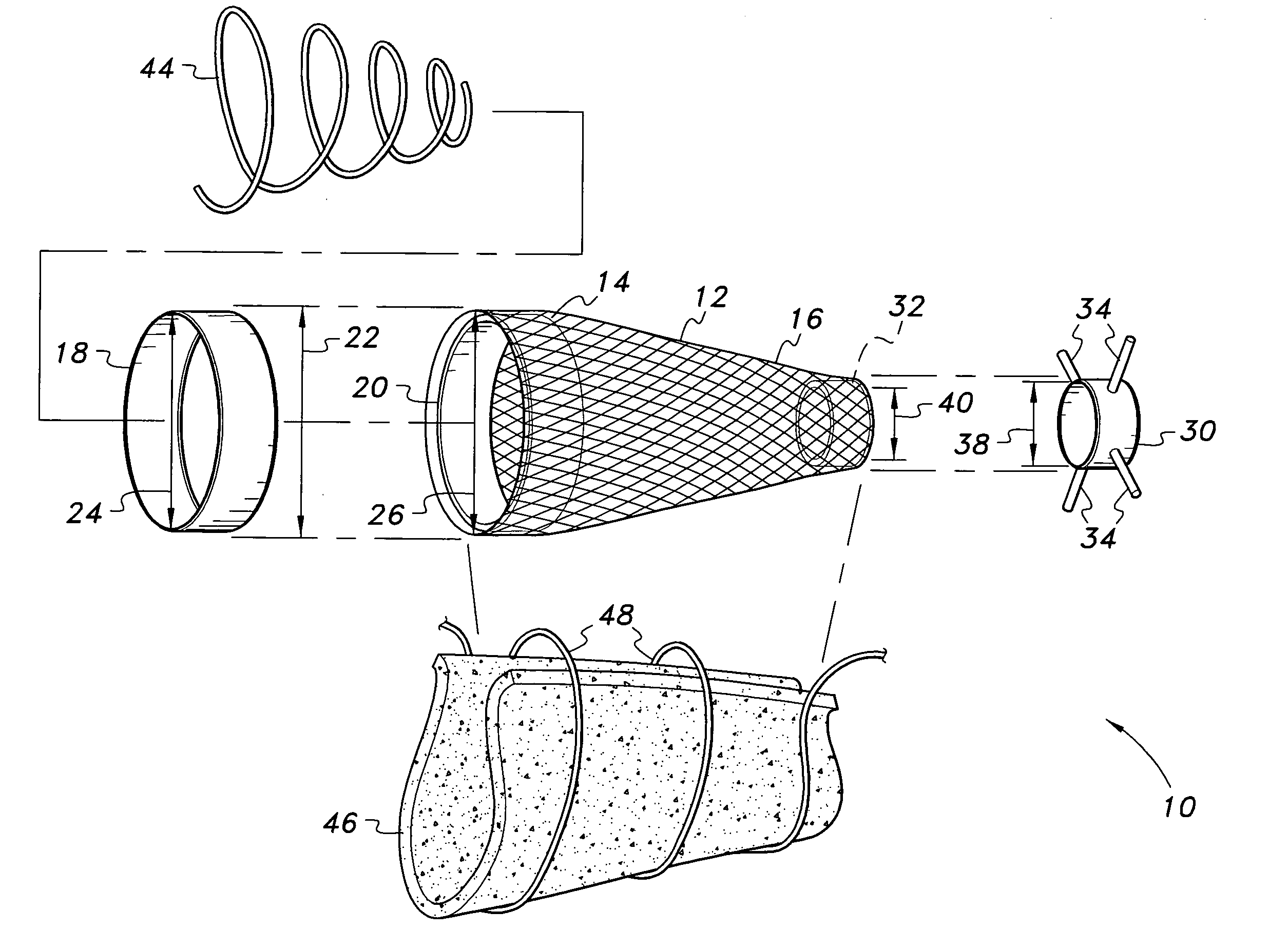
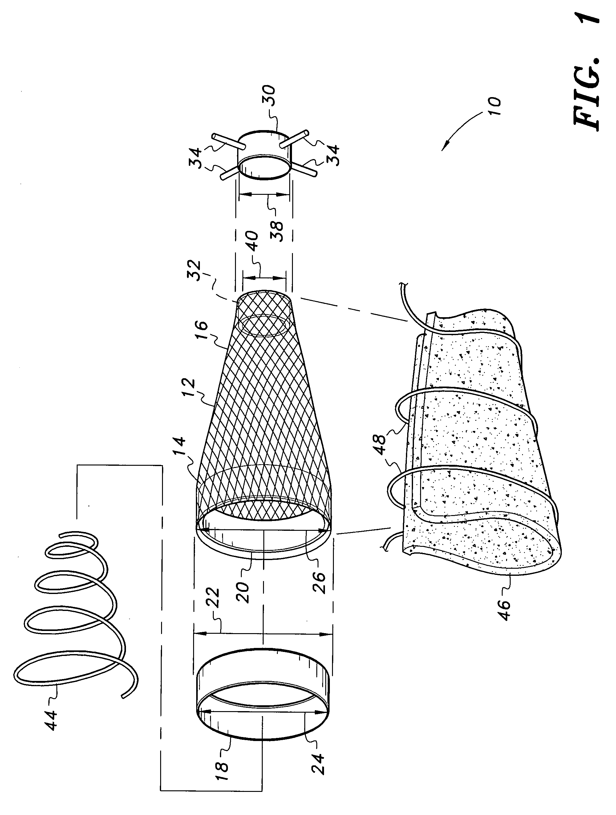
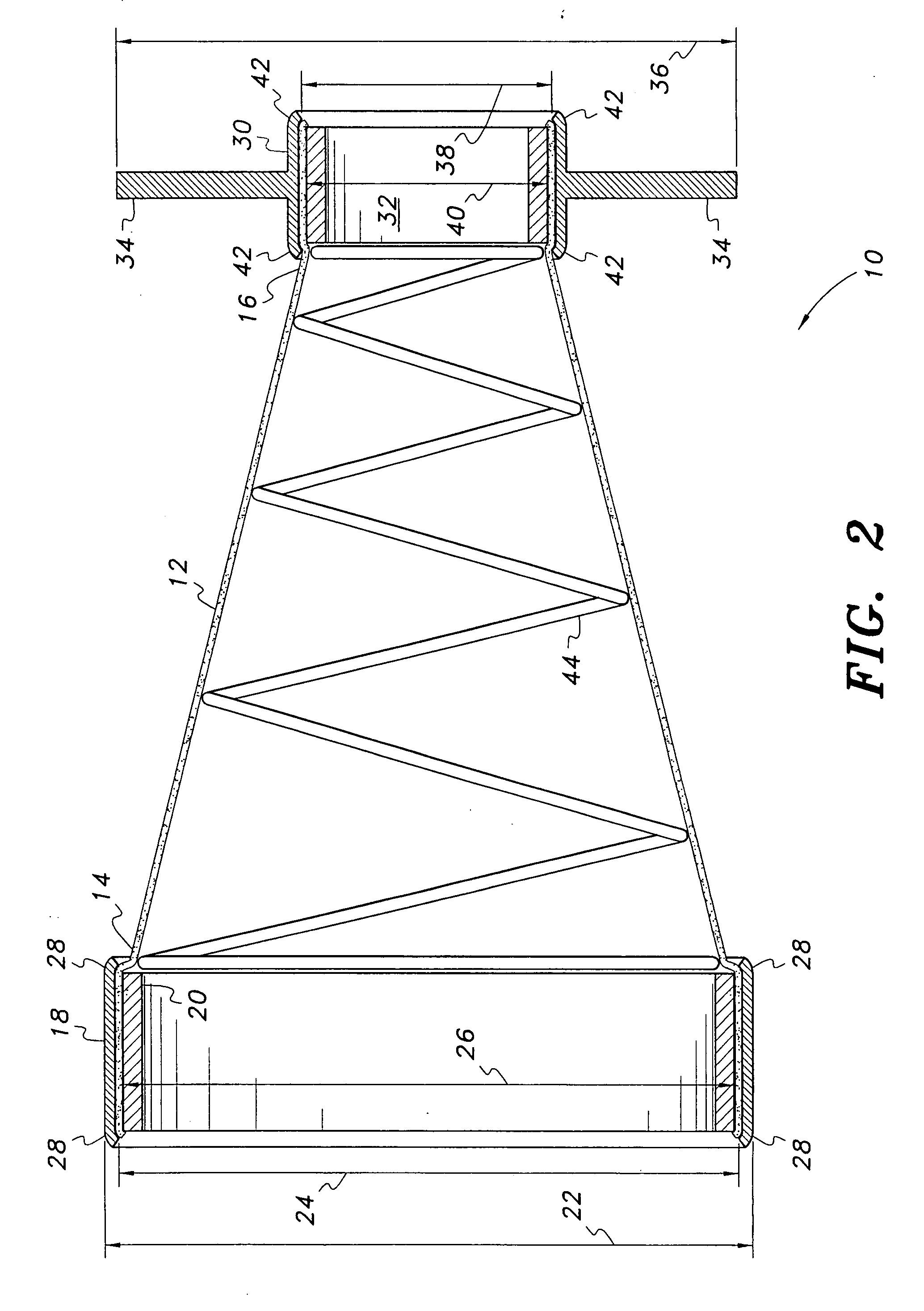
[0019]FIG. 1 of the drawings provides an exploded perspective view of an insert for an engine exhaust system, designated generally as 10, with FIG. 2 providing a side elevation view in partial section of the insert 10 of FIG. 1 without the optional external fiber batt covering shown in FIG. 1. The exhaust insert 10 of FIGS. 1 and 2 includes a frustoconical mesh component 12 formed of a woven, high temperature resistant material, e.g., corrosion resistant steel (i.e., “stainless” steel), glass or ceramic fiber, etc. Alternatively, a standard steel or other metal may be used, if desired. The material selected for the mesh component should provide sufficient porosity and flow-through to allow exhaust gases to pass therethrough without significant back pressure, and should be sufficiently flexible to allow for installation in a curved pipe by passing the insert 10 through the pipe and any curved portions thereof. A stainless steel braided mesh has been found to work well in testing, but...

embodiment 10

[0021]The larger diameter end 14 of the frustoconical mesh component 12 should retain its open shape to conform closely to the internal diameter of the exhaust pipe in order to avoid significant bypass of exhaust past the outer edge or surface of the mesh. This is accomplished by means of an attachment ring component secured to or about the larger diameter end 14 of the mesh component. In the embodiment 10 of FIGS. 1 and 2, the attachment ring component comprises concentric outer and inner attachment rings 18 and 20, which capture the larger diameter end 14 of the mesh component 12 therebetween. The larger diameter outer attachment ring 18 has an outer diameter 22 configured to fit closely within the inner diameter of the exhaust pipe in which the device is to be installed, and an inner diameter 24 configured to fit about the open end 14 of the mesh component 12. The inner attachment ring 20 has an outer diameter 26 configured to fit closely within the open end 14 of the mesh compon...

second embodiment

[0025]FIG. 3 of the drawings provides an illustration of an exhaust system insert, designated generally as 110 in the drawings. The insert 110 of FIG. 3 comprises a longitudinally symmetrical device having opposed mirror image portions. The insert 110 includes first and second frustoconical sections 112a and 112b, respectively, which are formed of any suitable porous mesh material (e.g., stainless or standard steel screen or mesh, glass fiber, ceramic mesh, etc.). Each section 112a and 112b includes a large diameter first end 114a and 114b and an opposite second end 116 of smaller diameter than the first end. It will be seen that the two frustoconical sections 112a and 112b of the mesh component form a continuous length extending between their opposite ends 114a and 114b, with the smaller diameter end 116 of each portion 112a and 112b being common between the two portions 112a and 112b. The two large diameter ends 114a and 114b are selected so that their outer diameters fit closely ...


PUM


Abstract

The insert for an engine exhaust system has at least one conical section of flexible mesh of metallic or other high temperature resistant fiber. Each section includes a rigid anchor or attachment ring having an outer diameter closely conforming to the inner diameter of the exhaust pipe, with the anchor ring being welded to the mesh material or the mesh being crimped between two concentric rings. A smaller diameter support ring may be provided at the opposite end of the conical mesh, with the support ring braced by a series of radial arms. A coil spring may be placed within the mesh for additional support, and/or the outer surface of the mesh may be wrapped with a glass fiber batt for additional sound control if desired. The device may serve to reduce the sound output of the exhaust system, and/or may serve as a spark arrestor as well.

Description

BACKGROUND OF THE INVENTION[0001]1. Field of the Invention[0002]The present invention relates generally to exhaust systems for internal combustion engines. More specifically, the present invention relates to inserts for engine exhaust systems for reducing or otherwise baffling or modifying the sound of the exhaust when the engine is in operation. The inserts may also serve as spark arrestors as well.[0003]2. Description of the Related Art[0004]While virtually all automobiles and trucks come equipped at the time of purchase with adequate sound suppression systems for their engines, this is not necessarily the case with many vehicles intended for off-road use. Personal watercraft and various racing and competition vehicles, wheeled or otherwise, may have relatively loud engine exhaust systems in order to reduce restrictive back pressure in the exhaust. In other cases, vehicle owners have modified the exhaust systems of their automobiles, motorcycles, etc. in an attempt to provide a di...

Claims


Application Information

Patent Timeline
IPC IPC(8): G10K11/00
CPCF01N1/24F01N13/02F01N2310/14F01N2230/06F01N13/1855
Inventor BALLARD, EBBIN C.
Owner BALLARD EBBIN C
Why Eureka
Try Eureka