Belt Connecting Method, Presetter, and Belt Connecting Apparatus

a belt connection and presetter technology, applied in the direction of manufacturing tools, transportation and packaging, other domestic objects, etc., can solve the problem of large number of presetters, and achieve the effect of reducing manufacturing costs

Active Publication Date: 2008-08-14
NITTA CORP
View PDF6 Cites 20 Cited by
  • Summary
  • Abstract
  • Description
  • Claims
  • Application Information

AI Technical Summary

Benefits of technology

[0040] Thus, the present invention eliminates the necessity for manufacturing a presetter per width of a belt, permitting a considerab...

Problems solved by technology

There is also a problem that successive insertions of the connecting portions having the s...

Method used


Image

  • Belt Connecting Method, Presetter, and Belt Connecting Apparatus
  • Belt Connecting Method, Presetter, and Belt Connecting Apparatus
  • Belt Connecting Method, Presetter, and Belt Connecting Apparatus

Examples


first preferred embodiment

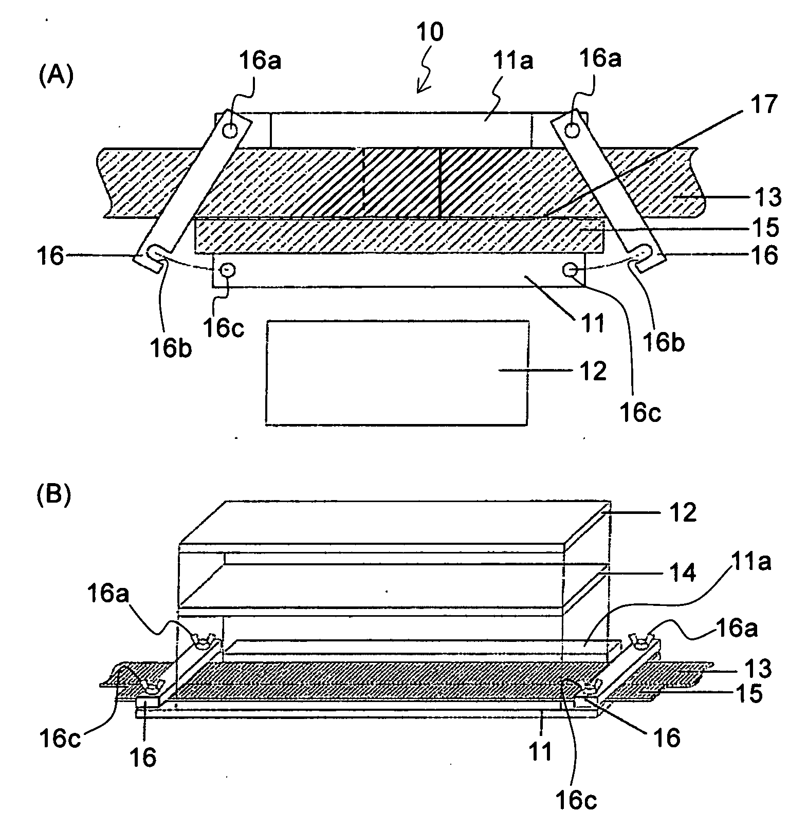
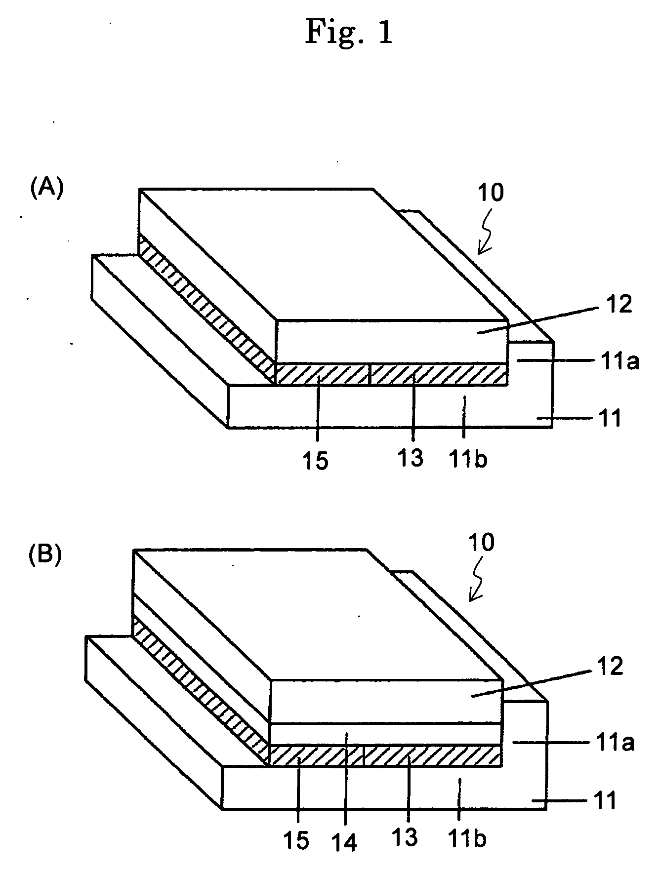
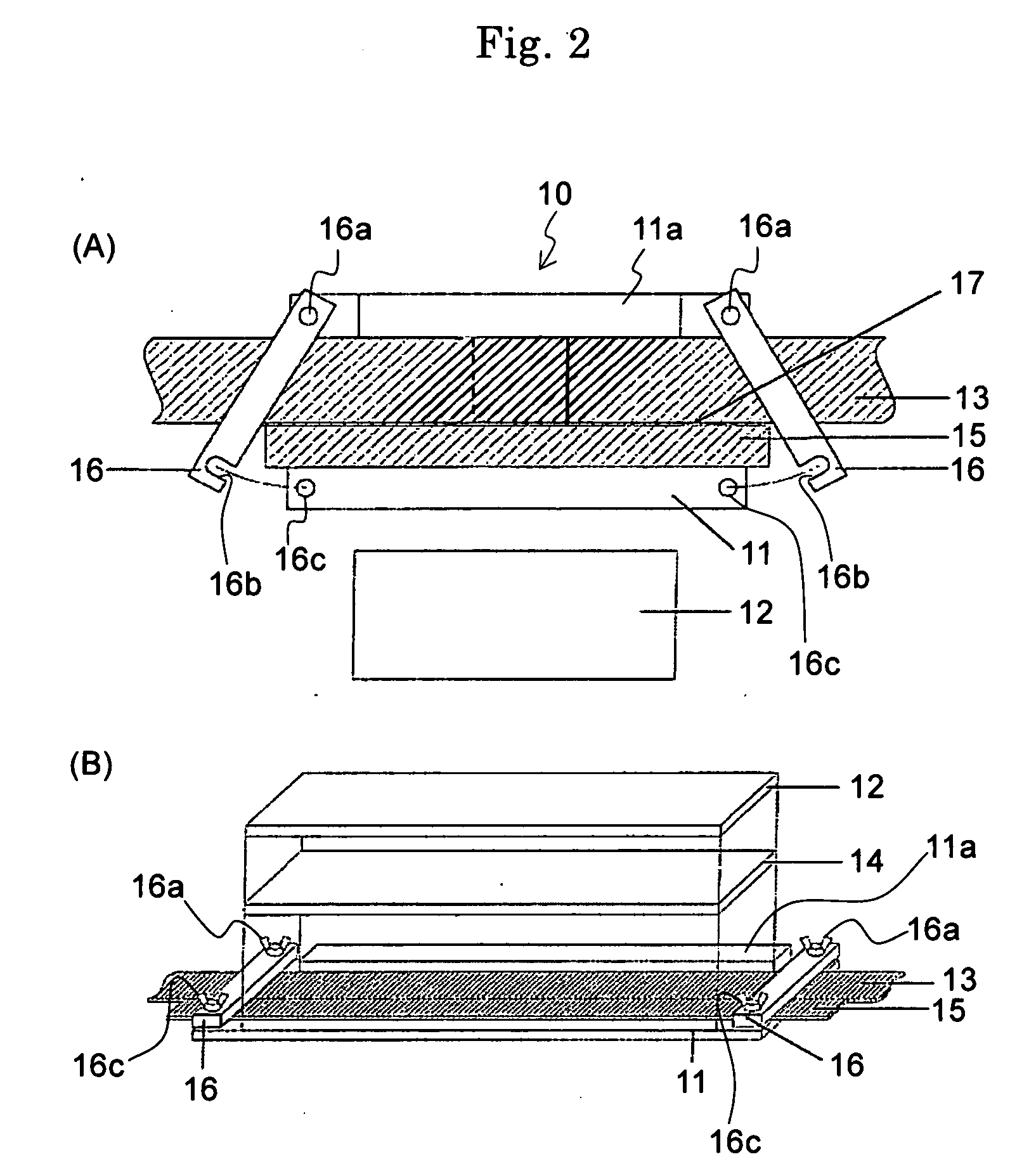
[0053] Preferred embodiments of the present invention will be described below with reference to the accompanying drawings. FIGS. 1A and 1B are schematic perspective views illustrating a presetter with a flat belt and a flat belt member fixed thereto in a belt connecting apparatus according to a first preferred embodiment of the present invention. Specifically, FIG. 1A is a schematic perspective view illustrating a presetter applied to a flat belt whose material is of a rubber type. FIG. 1B is a schematic perspective view illustrating a presetter applied to a flat belt whose material is of a resin type. FIG. 2A is a plan view illustrating the presetter of the first preferred embodiment. FIG. 2B is its exploded perspective view.

[0054] Referring to FIG. 1A to 2B, a presetter 10 has a lower mold 11 and an upper mold (a keep plate) 12. Connecting portions at both ends of a flat belt 13, and a flat belt member 15 having substantially the same compression property as the flat belt 13 are ...

second preferred embodiment

[0071] A second preferred embodiment of the present invention will next be described in detail with reference to the accompanying drawings. FIG. 4 is a schematic perspective view illustrating a presetter according to the second preferred embodiment. The second preferred embodiment differs from the first preferred embodiment in that a resin sheet 18 is further placed.

[0072] Specifically, the second preferred embodiment is intended for application to a case where the connecting portions of the flat belt 13 are subjected to end-to-end connection (i.e., an end-to-end connection type), as in the case with the finger shape. It is constructed and arranged so that both end surfaces to be connected in the flat belt 13 are shaped like a comb tooth, and the resin sheet 18 is set on the connecting portions and surroundings thereof in the flat belt 13, and an intermediate member 14 (e.g., a mesh mat, a cushion mat) and an upper mold (a keep plate) 12 are set on the resin sheet 18.

[0073] The re...


PUM

PropertyMeasurementUnit
Lengthaaaaaaaaaa
Adhesivityaaaaaaaaaa
Widthaaaaaaaaaa

Abstract

A method for enabling a presetter to connect connecting portions of belts having different widths, and for forming an endless connection of a flat belt with no defects such as the bend of the connecting portions. This method includes a first step of setting so that the connecting portions at both ends of the flat belt are placed on a lower mold surface of the presetter, and that, with the flat belt held from both sides by a wall part standing from the lower mold surface and a flat belt member having substantially the same compression property as the flat belt, an upper mold of the presetter is placed on the flat belt and the flat belt member, and then fixing the flat belt and the flat belt member by the presetter; and a second step of connecting the connecting portions at the both ends by pressing the presetter with the flat belt and the flat belt member fixed.

Description

BACKGROUND OF THE INVENTION [0001] 1. Field of the Invention [0002] The present invention relates to a connecting method of a belt such as a flat belt and a toothed belt for transmission or transportation, and to a presetter and a belt connecting apparatus that are used in the connecting method. [0003] 2. Description of Related Art [0004] Generally, the flat belt and the toothed belt for transmission or transportation are normally used with their both ends connected in an endless state. Examples of the shapes of connections of the flat belt are a skive (taper) shape, a step shape, and a finger shape. The shape of a connection of the toothed belt is a rectangular finger shape, and the like. To form a connection of any one of the shapes, connecting portions are temporarily laminated and then inserted into a cold platen press so as to be heated and pressurized. It is however necessary for an operator to be skilled in linearly laminating both ends of a belt with no bend. [0005] For this...

Claims


Application Information

Patent Timeline
IPC IPC(8): B24B27/02
CPCB29C65/02B29C65/48B29C65/7802B29C66/1142B29C66/855B29L2029/00B29C66/4324F16G3/16F16G3/10B29C66/4322B29C65/00B29C66/8322B29C66/49B29C66/71B29C66/1122B29K2021/00B29C65/78
Inventor TANIGUCHI, YASUAKITAMAKI, YOSHIROUKUBOTA, TAKESHI
Owner NITTA CORP
Why Eureka
Try Eureka