Electrode For Electrochemical Sensor

a sensor and electrochemical technology, applied in the field of electrochemical sensors, can solve the problems of electrode shorting or contamination of the interior of the well, enzymology to denature, and electrode shorting or contamination, and achieve the effects of reducing or avoiding damage to the electroactive substance, large surface area of electrodes, and large current carrying capacity

Inactive Publication Date: 2008-08-14
F HOFFMAN LA ROCHE LTD A K A F HOFFMANN LA ROCHE AG & HOFFMANN LA ROCHE LTD +1
View PDF16 Cites 22 Cited by
  • Summary
  • Abstract
  • Description
  • Claims
  • Application Information

AI Technical Summary

Benefits of technology

[0010]The device of the present invention comprises a strip containing a well-like structure having the working electrode of an electrochemical cell in its walls. A pseudo reference electrode is present in the form of a layer on top of the strip. The pseudo reference electrode is therefore not within the well itself, and will not contact any electroactive substance which is in the well. In this way, damage to the electroactive substance can be reduced or avoided.
[0011]Furthermore, the location of the pseudo reference electrode on top of the strip enables a large surface area of electrode to be used. The pseudo reference electrode therefore has a large current carrying capacity, which helps to avoid the cell current being limited by the pseudo reference electrode. The signal to noise ratio of the measurements may also be improved.
[0012]In a preferred embodiment of the invention, the pseudo reference electrode layer is not in contact with the perimeter of the first open part of the receptacle or partial receptacle. In this embodiment, even during insertion of the electroactive substance into the receptacle or partial receptacle, contact between the electroactive substance and the pseudo reference electrode layer is minimised.
[0014]The present inventors have surprisingly found that the device of the invention also provides very reliable results when a membrane is placed over the receptacle. The inventors have found that where a membrane is located between the working and counter electrodes of a cell, poor results may be achieved, possibly due to the high resistance of the membrane to the passing of ionic current. This appears to cause a potential drop across the membrane itself, such that the potential between the working and counter electrodes cannot be reliably controlled. In the device of the present invention, a membrane can be placed over the receptacle and adhered, for example, to the surface of the strip or to the pseudo reference electrode layer. The working and pseudo reference electrodes are both accessible to the sample after it has passed through the membrane. Ionic current therefore does not need to pass through the membrane or through a thin layer of sample adjacent to the membrane. The potential between the working and pseudo reference electrodes can therefore be more reliably controlled.
[0021]The process of the invention involves forming the receptacle by punching (or drilling or cutting) a hole in a laminate containing a working electrode layer. In one embodiment, the hole does not pass through the pseudo reference electrode layer that is located on a part of one surface of the laminate. Thus, the process of forming the hole does not cause contamination by drawing the pseudo reference electrode material down into the interior of the final receptacle. This, in turn, helps to reduce the possibility of electrode shorting.

Problems solved by technology

This can be detrimental to the electroactive substance, in particular where an enzyme is used since many materials employed as the counter and reference electrodes (e.g. Ag / AgCl) may cause enzymes to denature.
A further difficulty occurs when the reference / pseudo reference electrode is in the wall of the well.
Where the reference / pseudo reference electrode is present in this laminate structure, the process of forming a hole in the laminate draws the electrode material down into the well, potentially causing electrode shorting or contamination of the interior of the well.

Method used


Image

  • Electrode For Electrochemical Sensor
  • Electrode For Electrochemical Sensor
  • Electrode For Electrochemical Sensor

Examples


Embodiment Construction

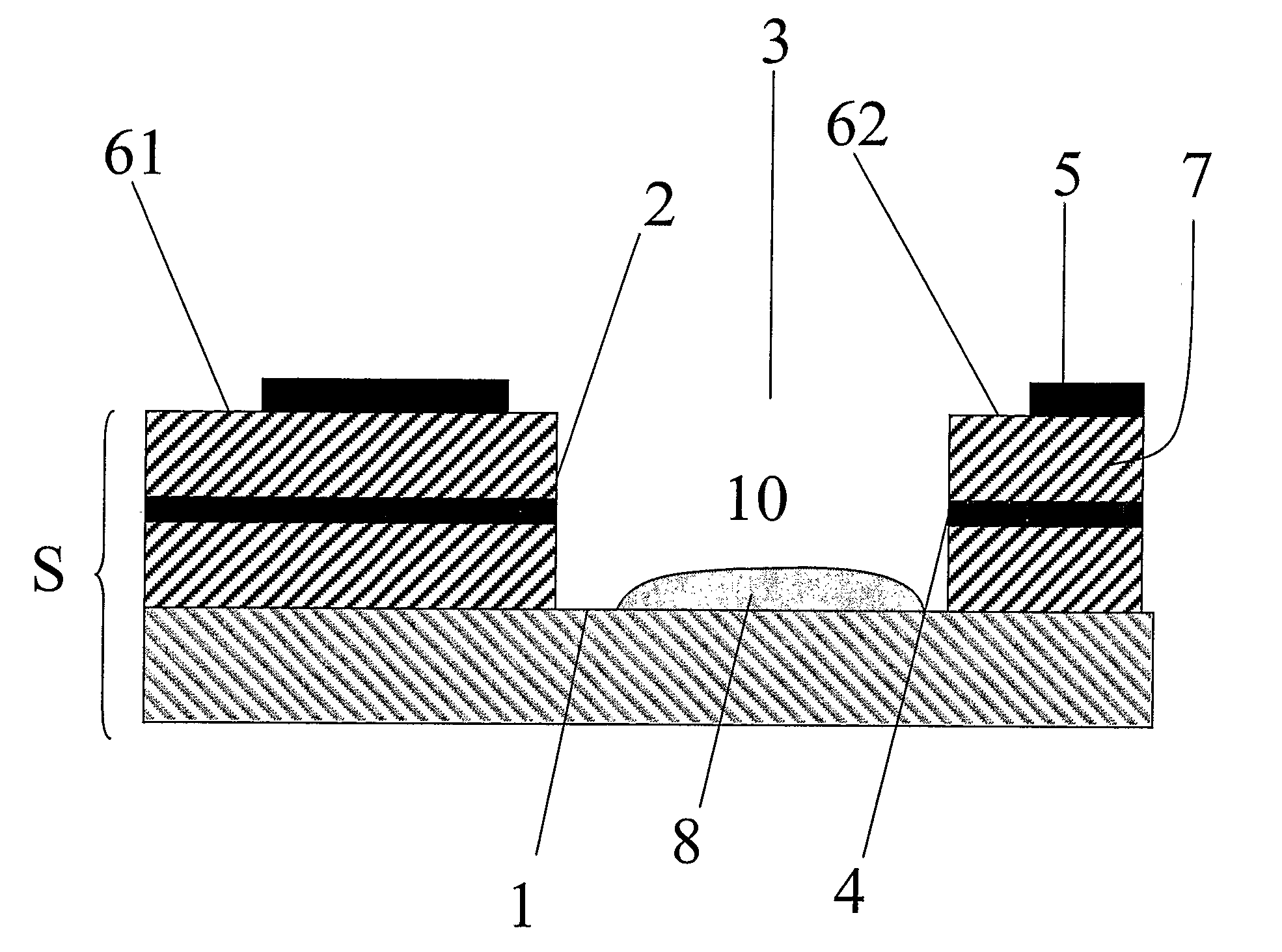
[0030]As used herein, a pseudo reference electrode is an electrode that is capable of providing a reference potential. The pseudo reference electrode may also act as a counter electrode. In this case, the pseudo reference electrode is typically able to pass a current without substantially perturbing the reference potential. Alternatively, a separate counter electrode may be provided, in which case the pseudo reference electrode typically acts as a true reference electrode and is, for example, a standard hydrogen or calomel electrode.

[0031]As used herein, a receptacle is a component, for example a container, which is capable of containing a liquid placed into it. A partial receptacle is a component which forms a receptacle when placed onto a substrate. Thus, a partial receptacle when placed on a substrate is capable of containing a liquid.

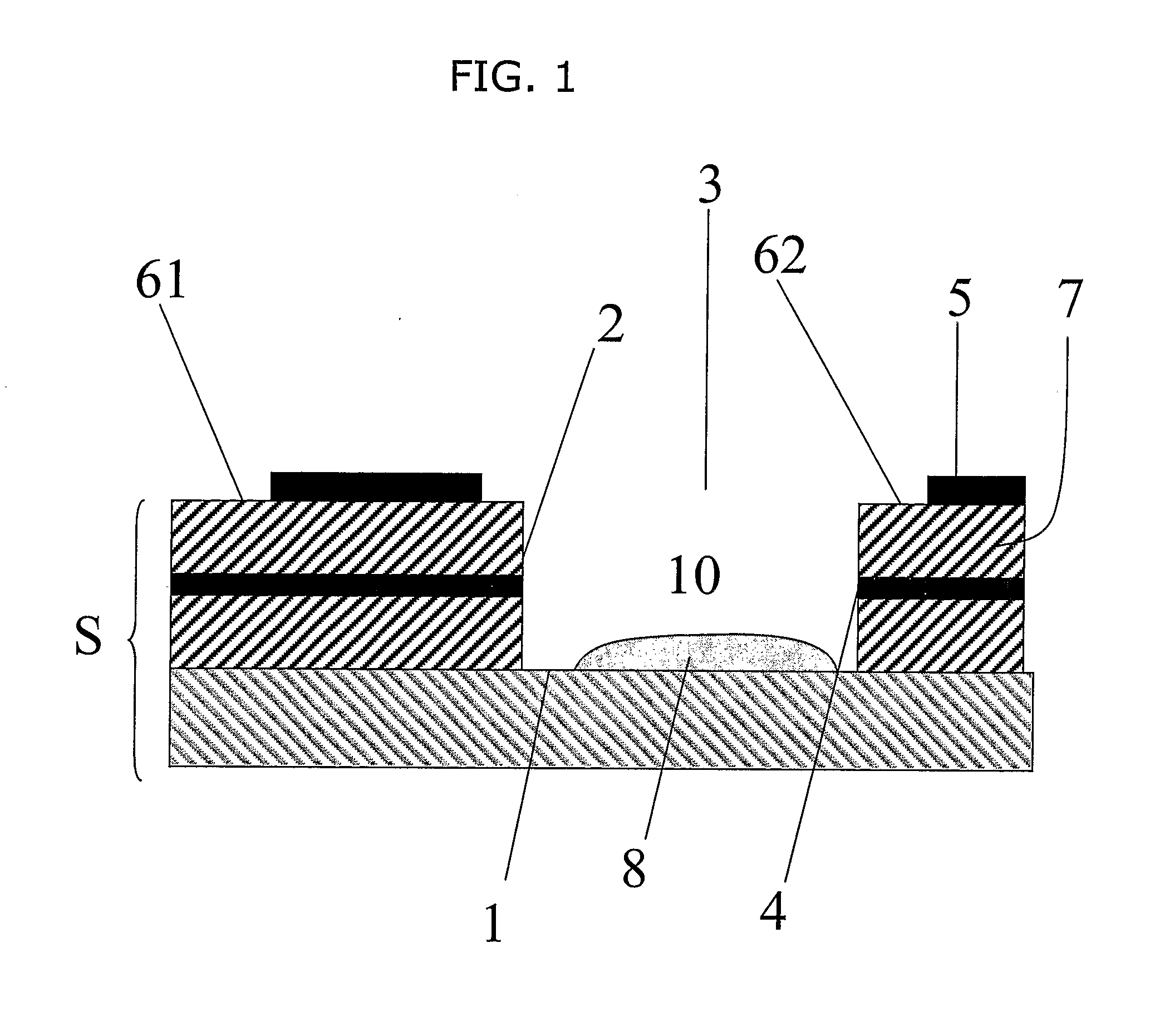
[0032]A first embodiment of the present invention is depicted in FIG. 1. In this embodiment, the device comprises a strip S. The strip S may have a...


PUM

PropertyMeasurementUnit
distanceaaaaaaaaaa
perimeteraaaaaaaaaa
volumeaaaaaaaaaa

Abstract

The invention concerns a device comprising an electrochemical cell. The device comprises a strip having a receptacle or partial receptacle formed therein. The working electrode of the electrochemical cell is in a wall of the receptacle or partial receptacle, and a pseudo reference electrode of the electrochemical cell is present as a layer on top of the surface of the strip. The device of the invention is useful in electrochemical sensing techniques.

Description

FIELD OF THE INVENTION[0001]The present invention relates to a device comprising an electrochemical cell, typically comprising a microelectrode for electrochemical detection, a process for manufacturing such a device and an electrochemical sensing method employing the device.BACKGROUND TO THE INVENTION[0002]Electrochemical cells containing microelectrodes are used for the electrochemical detection of various parameters of a substance. For example, such a cell may be used to detect, or measure the concentration of, a particular compound in a test substance. The use of electrochemical cells comprising microelectrodes as sampling devices brings a number of potential benefits including speed of operation, accuracy and minimal sample requirement. By using the microelectrodes in conjunction with enzymes or other electroactive substances it is possible to create sensors that provide quantitative measurement of target parameters through reactions with the corresponding electroactive substan...

Claims


Application Information

Patent Timeline
Patent Type & Authority Applications(United States)
IPC IPC(8): G01N27/00C12Q1/00G01N27/30
CPCC12Q1/002
Inventor HYLAND, MARK
Owner F HOFFMAN LA ROCHE LTD A K A F HOFFMANN LA ROCHE AG & HOFFMANN LA ROCHE LTD
Why Eureka
Try Eureka