Magnetically coupled valve actuator

a valve actuator and magnetic coupling technology, applied in the direction of valve operating means/release devices, water supply installation, transportation and packaging, etc., can solve the problems of increasing stress and eventual leakage, affecting the operation efficiency of the valve, and reducing the performance of the valve b, so as to avoid the use of bellows and increase the reliability of the system , the effect of high-speed valve operation

Inactive Publication Date: 2008-08-14
INTEVAC
View PDF5 Cites 43 Cited by
  • Summary
  • Abstract
  • Description
  • Claims
  • Application Information

AI Technical Summary

Benefits of technology

[0010]Various aspects of the subject invention provide an improved valve which provides isolation from the ambient and avoids the use of bellows, so as to increase the reliability of the system. A valve assembly and method of actuating a valve in a processing chamber through the use of magnetic force coupling is disclosed. The valve assembly comprises a valve rod for imparting a reciprocal motion to a valve blade which opens and closes a valve, the valve rod having at least one magnet mounted thereupon. A housing seals the valve rod and valve blade from the ambient, and an actuator rod in the ambient, having at least one complementary magnet mounted thereupon, aligns with the magnet on the valve rod to form a magnetic coupling through the housing. An actuator mechanism then provides a reciprocal motion to the actuator rod, which transfers the motion through the magnetic coupling to the valve rod and valve blade, thereby opening and closing the valve. The design allows for very high speed operation of the valve, low particle generation due to the absence of bellows, more robust vacuum isolation and lower maintenance costs.

Problems solved by technology

However, the movement of the bellows 140 traps particles in its folds, creating additional stress and eventual leaks, diminishing performance of the valve 120 over time.
Furthermore, since the valve 120 is opened and closed many times during processing, the seals in the air cylinders used to actuate the valve slowly wear out and cause unpredictable opening and closing times. Eventually, these leaks require repair of the worn components, halting the entire fabrication process while maintenance is performed.
Down time for systems such as these costs significant time and money.
Conventional systems may have over 20 such valves, where failure of a single bellows may require shutting down the entire system.

Method used


Image

  • Magnetically coupled valve actuator
  • Magnetically coupled valve actuator
  • Magnetically coupled valve actuator

Examples


Embodiment Construction

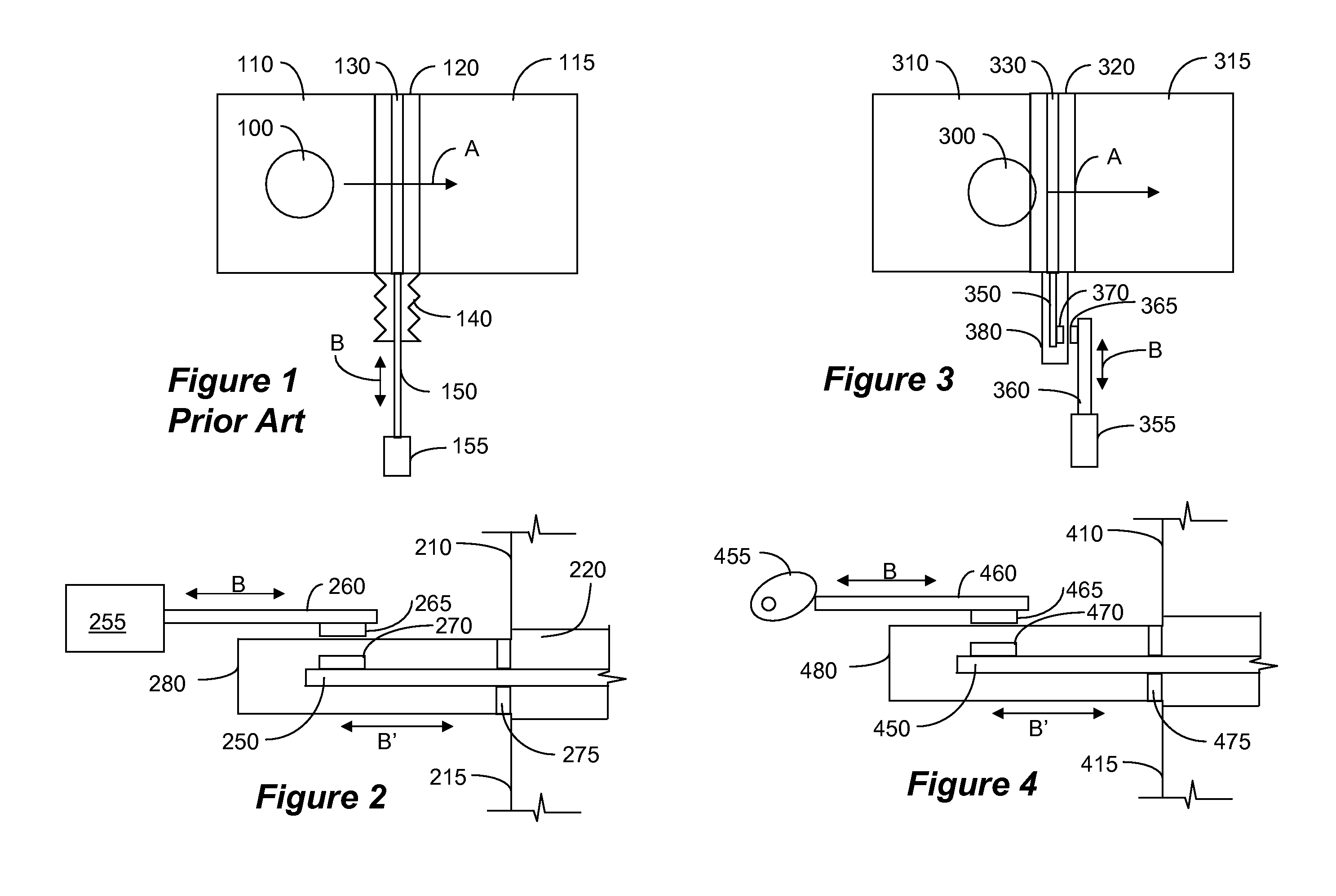
[0023]FIG. 2 is a schematic illustration of a valve arrangement according to an embodiment of the invention. As shown in FIG. 2, valve 220 (shown partially) separates chambers 210 and 215 (shown partially). The valve 220 includes a valve blade (not shown) that is activated by valve rod 250. Valve rod 250 is fitted with magnets 270, and is sealed from the ambient by a housing 280. The valve rod 250 is freely movable as shown by arrow B′ and is held in place by guides 275. On the other hand, actuator mechanism 255 actuates an actuation rod 260 in a reciprocal motion as shown by arrow B. The actuation rod 260 is also fitted with a magnet 265 that is the polar opposite of the magnet on the valve rod, creating an attractive magnetic field. Consequently, when the actuator rod 260 moves, the magnetic field of magnets 265 and 270 interact to form a magnetic coupling so that valve rod 250 follows the motion of actuator rod 260, to thereby move the valve blade and close and open the valve 220...


PUM


Abstract

A valve assembly and method of actuating a valve blade in a processing chamber through the use of magnetic force coupling is disclosed. The valve assembly comprises a valve rod for imparting a reciprocal motion to a valve blade which opens and closes a valve, the valve rod having at least one magnet mounted thereupon. A housing seals the valve rod and valve blade from the ambient, and an actuator rod in the ambient, having at least one complementary magnet mounted thereupon, aligns with the magnet on the valve rod to form a magnetic coupling through the housing. An actuator mechanism then provides a reciprocal motion to the actuator rod, which transfers the motion through the magnetic coupling to the valve rod and valve blade. Multiple actuator mechanisms can also be employed to vary the force applied to the valve blade to further increase the life of the valve assembly while still providing a strong seal between processing chambers. The design allows for very high speed operation of the valve with low maintenance costs.

Description

RELATED APPLICATIONS[0001]This application claims the benefit of priority to U.S. Provisional Application No. 60 / 889,254, filed Feb. 9, 2007, entitled “Magnetically Coupled Gate Valve Actuator,” the disclosure of which is incorporated herein in its entirety.BACKGROUND[0002]1. Field of the Invention[0003]The subject invention relates to an actuator of a valve enabling separation between two processing chambers of equal or different vacuum levels.[0004]2. Related Art[0005]Various fabrication equipment, such as semiconductor, flat-panel display, and hard disk drive use fabrication chambers that are pumped to an internal pressure different from the ambient, or atmosphere. Generally, these chambers operate under vacuum and require separation from one another during the fabrication process. Therefore, a valve is provided to enable loading and unloading of the work piece from one chamber to the next during the fabrication process. The valve is capable of forming a tight seal to prevent con...

Claims


Application Information

Patent Timeline
Patent Type & Authority Applications(United States)
IPC IPC(8): F16K31/08
CPCF16K3/0254F16K51/02F16K31/086Y10T137/0318
Inventor SCOLLAY, STUART
Owner INTEVAC
Why Eureka
Try Eureka