Cardiac pacemakers and systems and methods for using them

a pacemaker and cardiac cycle technology, applied in the field of implantable devices, can solve the problems of inability to obtain accurate pressure measurements at multiple points in time throughout the cardiac cycle, and inability to continuously directly measure the effect of the adjustment of the timing of electrical impulses without invasive measurements

Inactive Publication Date: 2008-08-14
RYAN TIMOTHY J
View PDF19 Cites 16 Cited by
  • Summary
  • Abstract
  • Description
  • Claims
  • Application Information

AI Technical Summary

Benefits of technology

[0006]The present invention is directed to implantable devices for measuring pressure and / or fluid impedance or resistance within the heart, e.g., for recording and / or determining pressure-volume loops. For example, the present invention may be directed to cardiac pacemakers, e.g., biventricular pacing apparatus and systems, and, more particularly, to pacemakers and / or pacing systems with resistance and / or pressure sensing capabilities, and to methods for using them. In exemplary embodiments, pacing leads may be placed in multiple locations within a heart, e.g., within the right ventricle and / or within the left ventricle or into a lateral coronary vein. One or both leads may include pressure sensing and / or fluid resistance sensing, e.g., for fluid volume approximation, which may provide substantially continuous measurement of the Pressure-Volume relationship, e.g., for determining the “PV Loop” for the heart. Such leads and / or pacemakers may provide accurate adjustment of the timing of delivery of electrical pulses to the various chambers of the heart, and / or may enable adjustment of the timing in near real-time, e.g., based on the filling and emptying performance of the cardiac chambers.

Problems solved by technology

Presently, there is no way to continuously directly measure the effects of adjustments of the timing of the electrical impulses without invasive measurements.
However, accurate pressure measurements at multiple points in time throughout the cardiac cycle cannot be obtained using echocardiography.

Method used


Image

  • Cardiac pacemakers and systems and methods for using them
  • Cardiac pacemakers and systems and methods for using them
  • Cardiac pacemakers and systems and methods for using them

Examples


Embodiment Construction

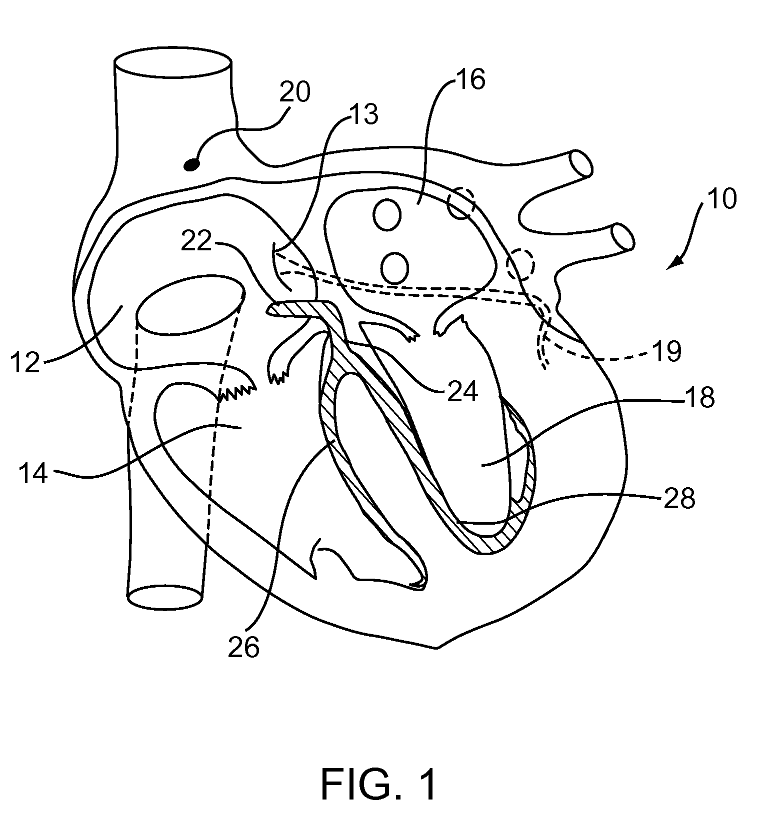
[0025]Turning to the drawings, FIG. 1 shows a cross-section of a heart 10, showing the various chambers of the heart, i.e., the right atrium 12, the right ventricle 14, left atrium 16, and left ventricle 18. In addition, FIG. 1 shows conduction pathways of the heart 10, e.g., the sinoatrial (“SA”) node 20, which is the impulse generating tissue in the right atrium 12, and the atrioventricular (“AV”) node 22, which includes the AV bundle or “Bundle of His”24. The AV bundle 24 splits into two branches, namely the right AV bundle branch 26, which activates the right ventricle 14, and the left AV bundle branch 28, which activates the left ventricle 18. The bundle branches 26, 28 taper out to produce numerous Purkinje fibers, which stimulate individual groups of myocardial cells to contract the chambers of the heart 10.

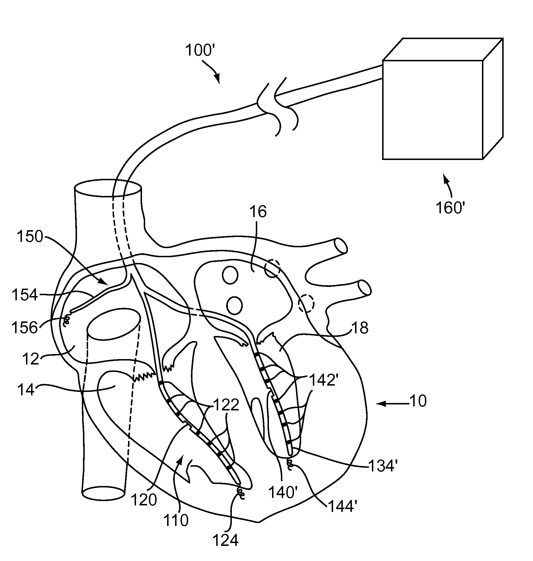
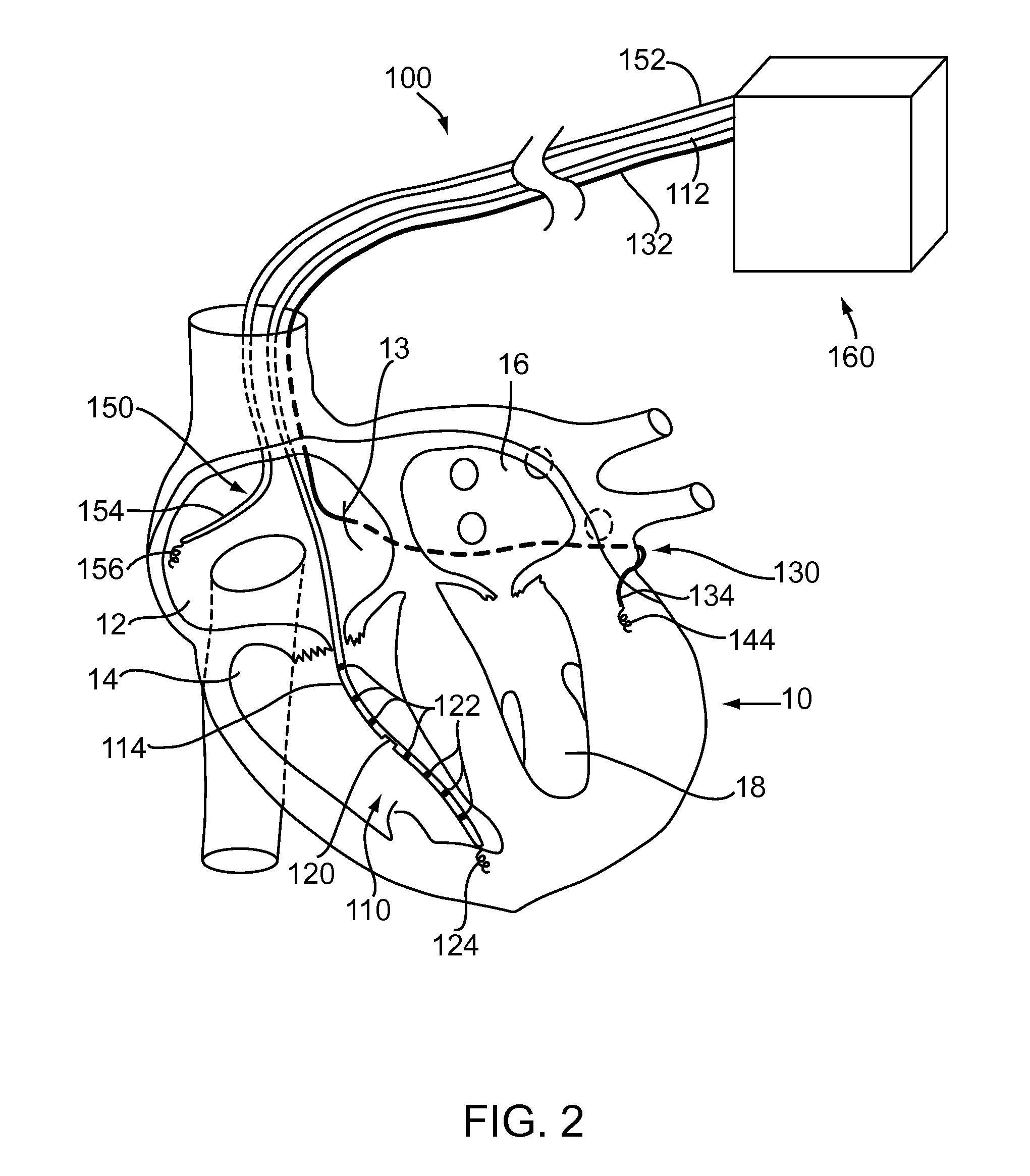
[0026]Turning to FIG. 2, an exemplary embodiment of a pacemaker system 100 is shown that may be implanted into a heart, such as the heart 10 of FIG. 1, e.g., for providing...


PUM


Abstract

Systems and methods are provided for determining the pressure-volume relationship for one or more chambers of a heart. An implantable device includes a catheter including a distal end sized for introduction into a chamber of a heart, a pressure sensor for measuring pressure within the chamber, and a resistance sensor for measuring fluid resistance within the chamber. A processor coupled to the catheter obtains pressure data from the pressure sensor and fluid resistance data from the resistance sensor. The processor approximates fluid volume within the chamber as a function of time and determines one or more pressure-volume loops based upon the pressure data and the fluid volume. In one embodiment, the catheter is a lead including a pacing electrode and a controller including the processor delivers pulses to the pacing electrode based upon the pressure-volume loops to deliver electrical therapy to the heart.

Description

[0001]This application claims benefit of co-pending provisional application Ser. No. 60 / 882,976, filed Dec. 29, 2006, the entire disclosure of which is expressly incorporated by reference herein.FIELD OF THE INVENTION[0002]The present invention relates generally to implantable devices for measuring pressure and fluid volume within the heart, for example, cardiac pacemakers, e.g., biventricular pacing systems, and, more particularly, to pacemakers and / or pacing systems with resistance and / or pressure sensing capabilities, and to methods for using them.BACKGROUND[0003]Implantable cardiac pacemakers are implanted within patients' hearts, e.g., for pacing, sensing and / or defibrillation, e.g., within the right and / or left chambers of the heart. Leads may sense electrical activity of the heart and pacemakers coupled to the leads may provide pacing as needed, depending on the mode of pacing employed. Biventricular pacing has been successfully employed to improve cardiac output in patients ...

Claims


Application Information

Patent Timeline
Patent Type & Authority Applications(United States)
IPC IPC(8): A61N1/368
CPCA61B5/02028A61B5/0215A61B5/053A61N1/36564A61N1/3627A61N1/36521A61B5/0538
Inventor RYAN, TIMOTHY J.
Owner RYAN TIMOTHY J
Why Eureka
Try Eureka