
Mold oscillating apparatus

a technology of oscillating apparatus and moving bearing, which is applied in the direction of dough shaping, manufacturing tools, applications, etc., can solve the problems of limited flexural deformation of the connecting beam, and space between the moving bearing housings not supported and held up in the air, and achieves sufficient deformation

Active Publication Date: 2008-08-21
KOBE STEEL LTD
View PDF1 Cites 5 Cited by
  • Summary
  • Abstract
  • Description
  • Claims
  • Application Information

AI Technical Summary

Benefits of technology

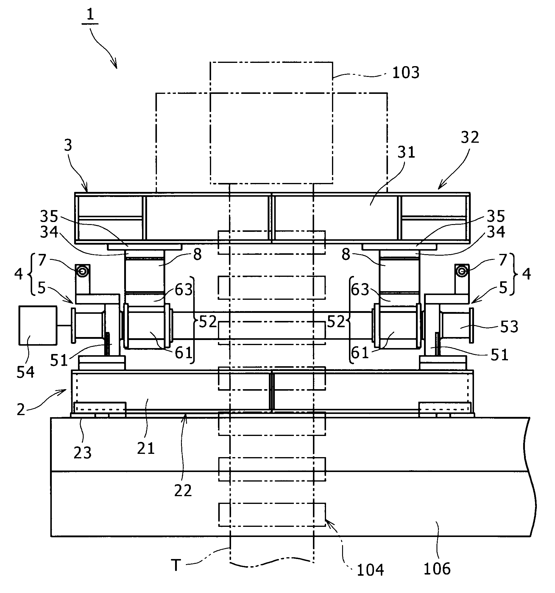
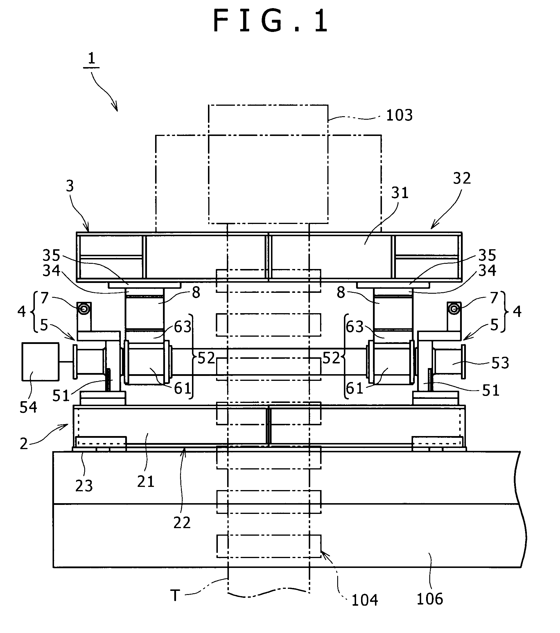
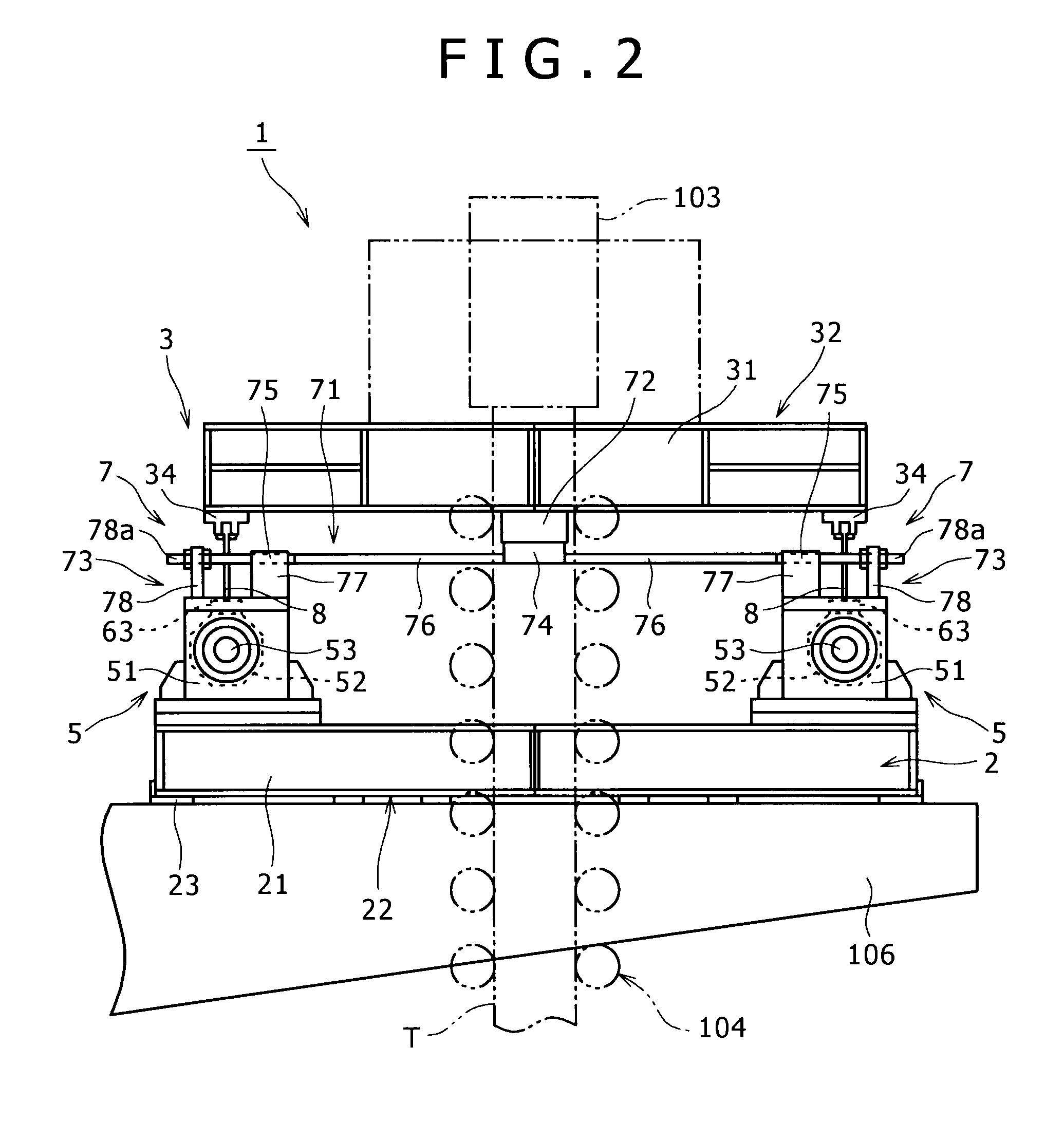
[0012]It is an object of the present invention to provide a mold oscillating apparatus capable of eliminating torsional deformation of a connecting member for interconnecting moving bearing housing moved by eccentric rotation of eccentric shafts and a mold table oscillated by rotation of the moving bearing housing, and easing a stress generated in the connecting member.

Problems solved by technology

However, in the connecting beam according to the above mold oscillating apparatus, although the both ends of the lower end part are supported by the moving bearing housing, a space between the moving bearing housings is not supported and held up in the air.
Therefore, flexural deformation of the connecting beam due to the motion of the moving bearing housing is limited to interconnecting portions of the moving bearing housing on the both sides and the vicinity thereof.
Since the connecting beam receives a cyclic stress due to oscillation of the mold, there is a fear that even a relatively small stress generated causes crack and finally leads to breakage.
However, since the connecting beam itself is a large sized part, the exchange is extremely uneconomical and an exchange work is not easy.

Method used


Image

  • Mold oscillating apparatus
  • Mold oscillating apparatus
  • Mold oscillating apparatus

Examples


Embodiment Construction

[0047]Hereinafter, an embodiment of the present invention will be specifically described along the drawings.

[0048]As shown in FIG. 9, in a continuous casting assembly 100 having a mold oscillating apparatus 1 according to the present invention, a tundish 102 is arranged on the lower side of a ladle 101, a mold 103 is arranged on the lower side of the tundish 102, a secondary cooling belt 104 including a plurality of support rolls and cooling sprays extends taking the lower side of the mold 103 as a starting end part, and a drawing apparatus 105 is arranged in a terminal end part of the secondary cooling belt 104. Molten steel T flown from the ladle 101 to the tundish 102 is formed into a shape and then drawn by the support rolls of the secondary cooling belt 104 and the drawing apparatus 105. Therefore, the molten steel T is cooled down when passing through the secondary cooling belt 104 so that a slab (or bloom, billet) is formed.

[0049]The ladle 101 is mounted on a swing tower 107....


PUM

PropertyMeasurementUnit
lengthaaaaaaaaaa
lengthaaaaaaaaaa
thickness t2aaaaaaaaaa

Abstract

In a mold oscillating apparatus according to the present invention, a connecting plate for interconnecting a moving bearing housing rotated by eccentric rotation of an eccentric shaft and a mold table oscillated by rotation of the moving bearing housing is supported by the mold table from one end of an upper end part thereof to the other end, and supported by the moving bearing housing from one end of a lower end part thereof to the other end. By such a configuration, torsional deformation of the connecting plate is prevented and a stress generated in the connecting plate is eased.

Description

BACKGROUND OF THE INVENTION[0001]1. Field of the Invention[0002]The present invention relates to a mold oscillating apparatus for oscillating a mold forming a continuous casting assembly.[0003]2. Description of the Related Art[0004]Currently, in the continuous casting assembly, there is a known technique of using a mold oscillating apparatus for generating relative motion between a mold inner wall and a slab by oscillating a mold. By the relative motion, inflow of flux between the mold inner wall and the slab is facilitated and thereby adhesion of the slab to the mold inner wall is prevented.[0005]For example, U.S. Pat. No. 4,678,022 discloses a mold oscillating apparatus for fixedly mounting and interconnecting a mold table in which a mold is installed and a moving bearing housing to each other by a connecting beam.[0006]In the mold oscillating apparatus, the moving bearing housing fitted onto both end parts of a drive shaft through a bearing and moved by eccentric rotation of the ...

Claims


Application Information

Patent Timeline
Patent Type & Authority Applications(United States)
IPC IPC(8): B22D27/08B29C37/00
CPCB22D11/053
Inventor KAWAGUCHI, HIROSHISASAKI, HIROFUMI
Owner KOBE STEEL LTD
Learn More