Variable gain amplifier circuit and filter circuit

a filter circuit and amplifier circuit technology, applied in the field of amplifier circuits, can solve problems such as distortion of signal waveforms amplified by circuits

Active Publication Date: 2008-08-21
FUJITSU LTD
View PDF7 Cites 18 Cited by
  • Summary
  • Abstract
  • Description
  • Claims
  • Application Information

AI Technical Summary

Benefits of technology

[0011]It is an object of the present invention to provide a variable gain amplifier circuit in which the amount of feedback does not vary even when changing gain to use it in various circuits.

Problems solved by technology

Such a phase characteristic change can cause distortion in the waveform of a signal amplified by the circuit.

Method used


Image

  • Variable gain amplifier circuit and filter circuit
  • Variable gain amplifier circuit and filter circuit
  • Variable gain amplifier circuit and filter circuit

Examples


Embodiment Construction

[0050]The preferred embodiments of the present invention are described in reference to the drawings.

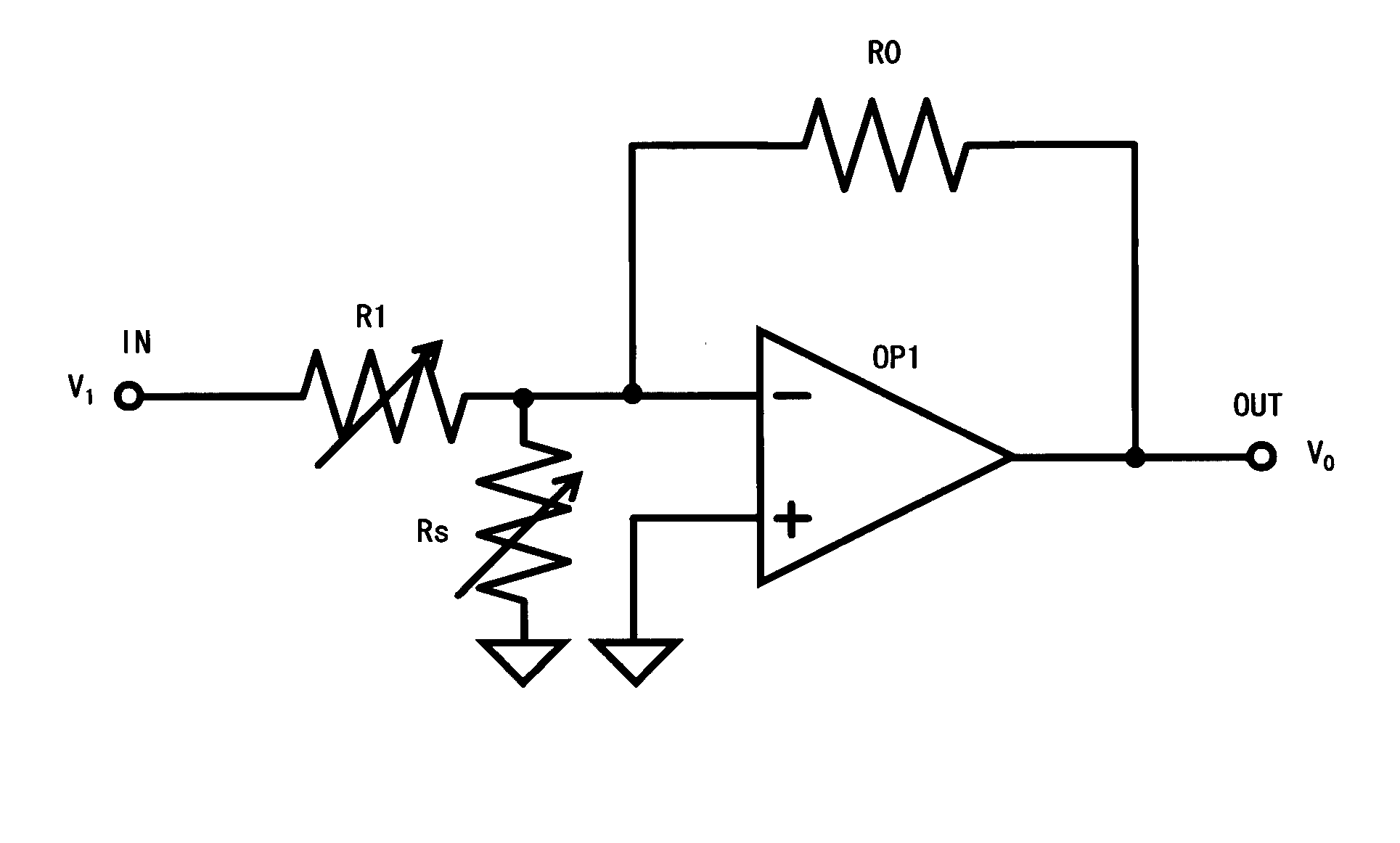
[0051]Firstly, FIG. 3 is described. FIG. 3 shows the first configuration example of the variable gain amplifier circuit implementing the present invention.

[0052]In FIG. 3, the non-inversion input terminal of the operational amplifier OP1 is connected to the ground (or reference potential). A feedback resistor R0 is connected between the output terminal and the inversion input terminal of the operational amplifier.

[0053]An input resistor R1 is connected between the input terminal IN of this variable gain amplifier circuit and the inversion input terminal of the operational amplifier. The resistance value of this input resistor R1 is variable.

[0054]Furthermore, an adjustment resistor Rs is connected to the inversion input terminal of the operational amplifier and the ground (or reference potential) of the circuit. The resistance value of this adjustment resistor is also variable.

[0055]T...


PUM


Abstract

This variable gain amplifier is provided with an operational amplifier. The non-inversion input terminal of the operational amplifier is connected to a reference potential. A feedback resistor is connected between the output terminal and inversion input terminal of the operational amplifier. An input resistor is inserted between the inversion input terminal of the operational amplifier and the input terminal of the variable gain amplifier circuit. An adjustment resistor is connected between the inversion input terminal of the operational amplifier and the reference potential. The resistance value of the adjustment resistor is controlled in such a way as to maintain constant against the resistance value change a combined resistance value in its parallel connection with the input resistor when changing the resistance value of the input resistor.

Description

BACKGROUND OF THE INVENTION[0001]1. Field of the Invention[0002]The present invention relates to the amplification technology of electric signals, and more particularly to the technology of an amplifier circuit whose gain can be varied.[0003]2. Description of the Related Art[0004]FIG. 1 is explained. FIG. 1 is one example of a variable gain amplifier circuit whose gain can be changed.[0005]In FIG. 1, the non-inversion input terminal of an operational amplifier OP1 is connected to the ground (reference potential, virtual earth) of the circuit. A feedback resistor R0 is connected between the output terminal and inversion terminal of the operational amplifier.[0006]An input resistor R1 is connected between the input terminal IN of this variable gain amplifier circuit and the inversion input terminal of the operational amplifier OP1. The resistance value of this input resistor R1 can be changed.[0007]An amplifier circuit with a configuration such as that shown in FIG. 1 is a typical inv...

Claims


Application Information

Patent Timeline
Patent Type & Authority Applications(United States)
IPC IPC(8): H03G3/20H03F1/36
CPCH03F1/08H03F1/34H03F3/45475H03F2200/153H03F2200/264H03G1/04H03F2203/45522H03F2203/45526H03F2203/45528H03F2203/45591H03G1/0035H03F2203/45136
Inventor OISHI, KAZUAKI
Owner FUJITSU LTD
Why Eureka
Try Eureka