Backlight module

a backlight module and backlight technology, applied in the field of backlight modules, can solve the problems of increasing the brightness of lcds and the color saturation of images, many problems to be solved, and troublesome control, so as to enhance the front-side illuminance of the backlight module, reduce the additional manufacturing cost, and enhance the color saturation of the light source

Inactive Publication Date: 2008-08-21
WINTEK CORP
View PDF6 Cites 8 Cited by
  • Summary
  • Abstract
  • Description
  • Claims
  • Application Information

AI Technical Summary

Benefits of technology

[0013]The efficacy of the present invention involves using three color lights with different wavelengths as the backlight sources and also using the light guide portion with its optical paths exactly designed, so as to enhance the color saturation of the light source. Thus, different color lights can be uniformly mixed into the white light. The “V-shaped” light guide portion can give a preferred directionality of the light rays coming out from the light exit surface, and thereby enhancing the front-side illuminance of the backlight module, which can be used to solve the problems existing in the prior art. The present invention can also reduce the additional manufacturing cost resulting from using the high purity color filter and high brightness LED or using an increased number of LEDs, and thus the products and prices can meet the market requirements.

Problems solved by technology

However, the requirement on the brightness of LCDs and the color saturation of images grows increasingly.
However, there are still many problems to be solved.
However, the LEDs of three colors are packaged into an encapsulated housing, and then the ON / OFF and intensity of the three LEDs are controlled respectively, thus causing troubles in control.
Therefore, if the red, blue, and green LEDs are lit up, the lights of three colors cannot be uniformly mixed into the white light.
Therefore, the color purities of the red light frequency spectrum and the green light frequency spectrum contained in the yellow light frequency spectrum are not high, so it cannot meet the requirements on the color saturation of LCDs.
Therefore, in the above technologies, in order to produce LCDs with high color saturation and brightness, high-purity color filters and high-brightness LED must be used or the number of LEDs must be increased, which relatively enhances the manufacturing cost of the backlight module.

Method used


Image

  • Backlight module
  • Backlight module
  • Backlight module

Examples


first embodiment

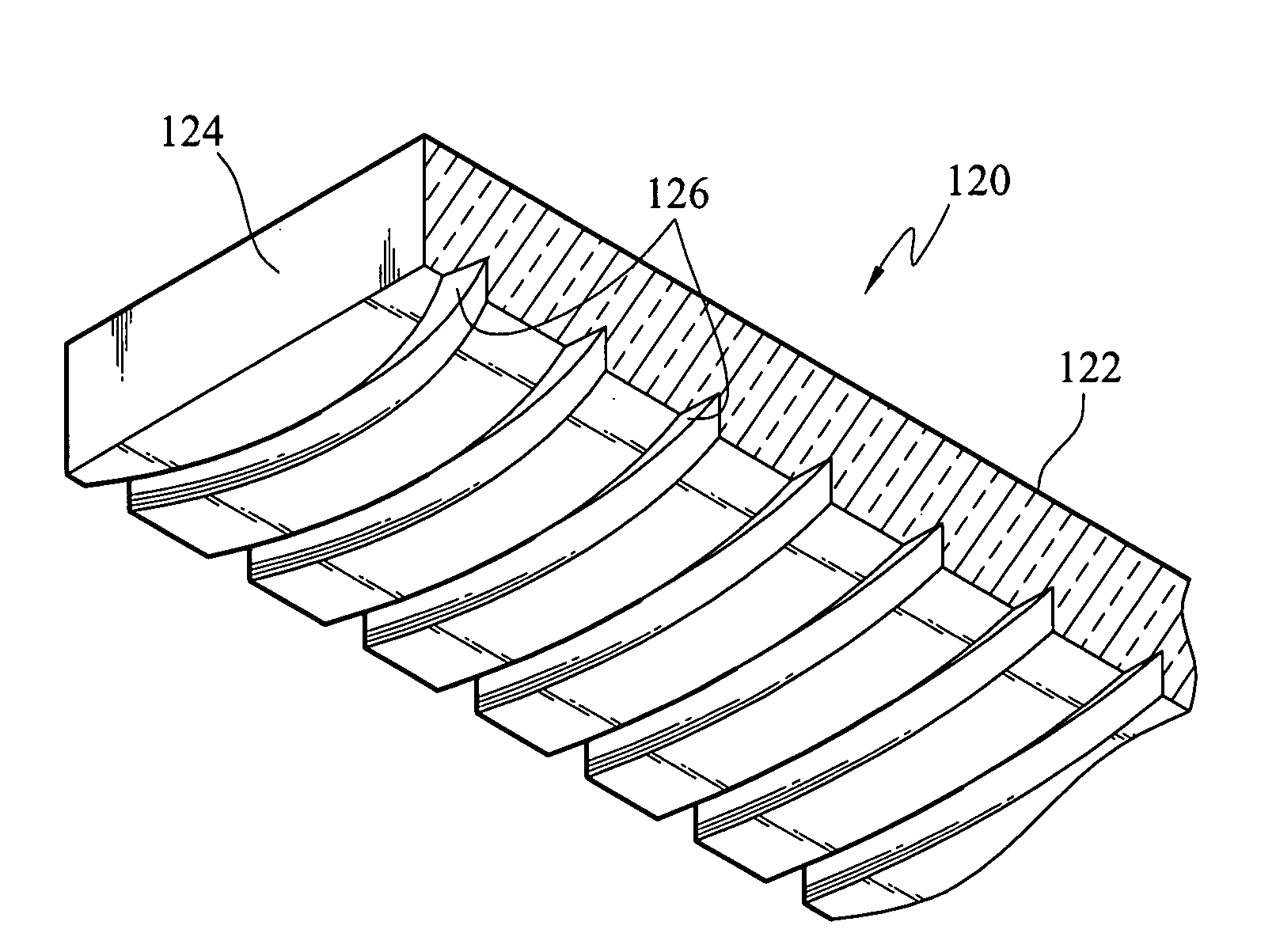
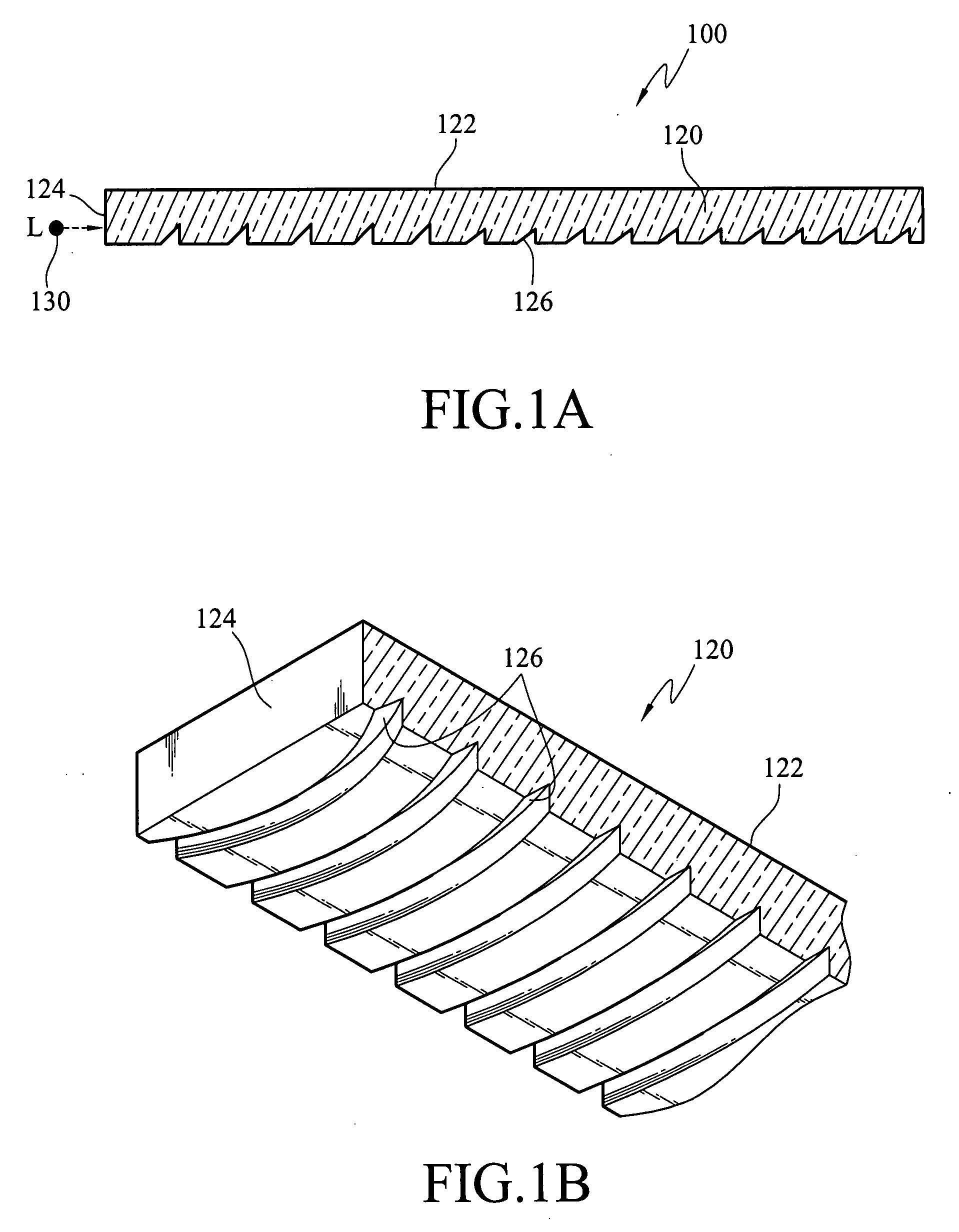
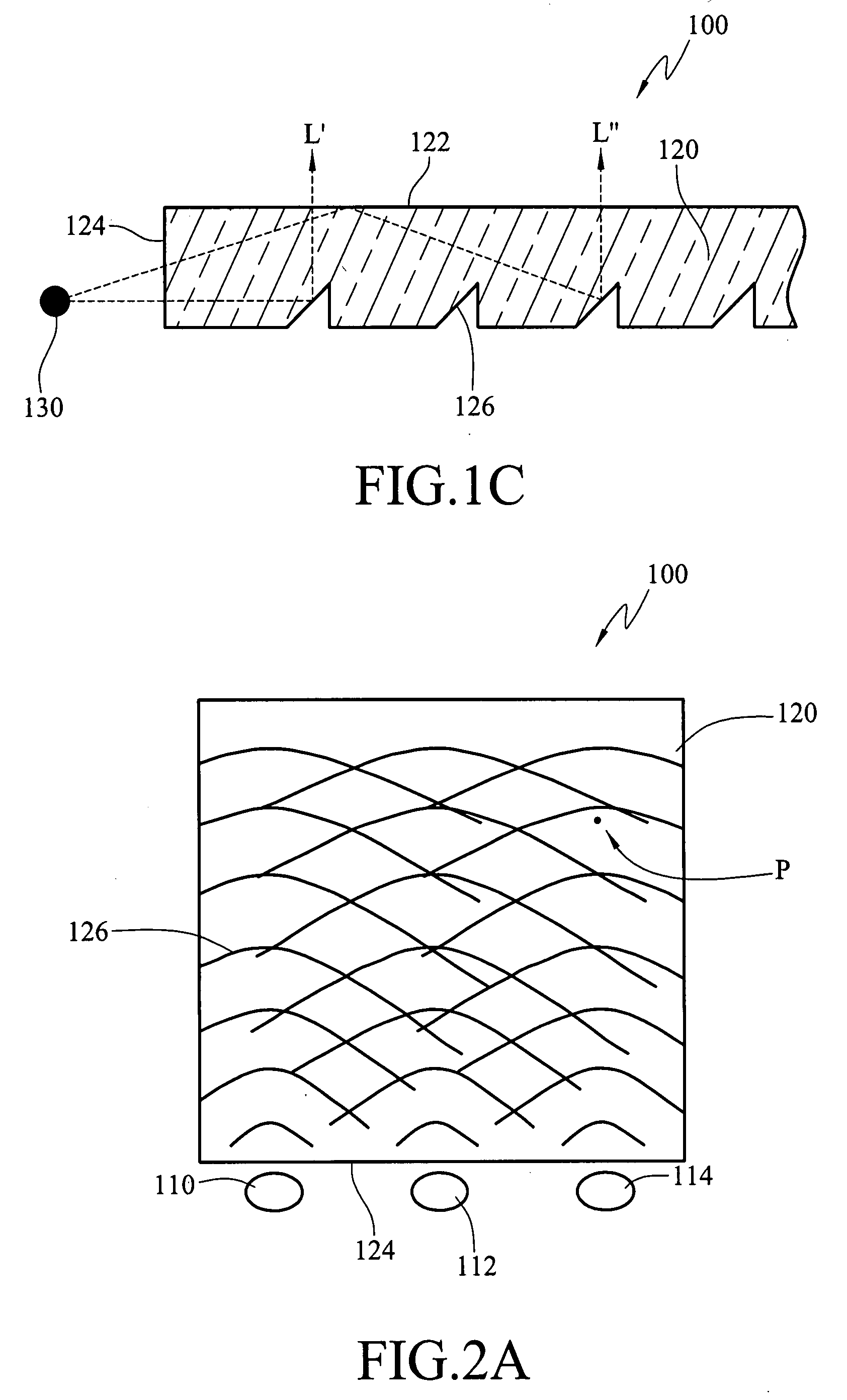
[0031]Referring to FIG. 1C, a schematic view of the guiding of the lights according to the backlight module of the present invention. As shown in FIG. 1C, the backlight module 100 has a light guide plate 120 and a light source 130. The light guide plate 120 includes a light entrance surface 124, a light exit surface 122, and a plurality of “inverted-V” light guide portions 126 depressed inward the light guide plate. The light entrance surface 124 is a side surface of the light guide plate 120 adjacent to the light source 130 for the lights L′ and L″ to be irradiated therein. The light exit surface 122 is a top surface adjacent to the light entrance surface 124 for projecting the lights L′ and L″. The “inverted-V” light guide portions 126 are located on a bottom surface corresponding to the light exit surface 122, and are continuously extended groove structure, so as to guide the incident lights L′ and L″ in the normal line direction of the light exit surface 122. Each of the “invert...

third embodiment

[0040]Definitely, the numbers and relative positions of the light sources of the backlight module 600 in the present invention are also as those as shown in FIGS. 2B, 2C, and 2D, that is, the light sources used are not limited to three kinds, and the incident light is not limited to enter the light guide plate 120 from the same light entrance surface 124, and also the position of the light source is not limited in this embodiment. In addition, the backlight module 600 in this embodiment can also be operated with the driving method of field sequential.

[0041]Referring to FIG. 5, an isometric view of the light guide plate structure according to a fourth embodiment of the backlight module of the present invention. Most of the structures of the light guide plate in this embodiment are the same as that of the third embodiment, and the main difference lies in that the light guide plate 120 includes “V-shaped” light guide portions 129 with non-continuously extended structures in addition to...


PUM


Abstract

A backlight module has a light guide plate and a plurality of light sources. The light guide plate includes a light exit surface, a plurality of light entrance surfaces round the light exit surface, and a plurality of light guide portions disposed on the bottom surface opposite to the light exit surface. The light guide portions corresponding to the same imaginary circle center constitute a concentric arc-shaped light guide portion set. The imaginary circle center of each light guide portion set is located at the outer side of the light entrance surfaces. Light rays projected to one of the light entrance surfaces from the imaginary circle center of each light guide portion set are guided to a light exit surface by the light guide portion set. The wavelength of the light ray projected by each light source is not equal to that of the light projected by another light source.

Description

BACKGROUND OF THE INVENTION[0001]1. Field of Invention[0002]The present invention relates to a backlight module, and more particularly, to a backlight module using a light emitting diode for enhancing color saturation of a liquid crystal display (LCD).[0003]2. Related Art[0004]With the tremendous progress of science and technology and high development of network, multimedia technique, image data transmission, the demanding for multimedia displays is greatly increasing. In recent years, LCDs having the advantages of thin thickness, light weight, portability, and low radiation compared with conventional Cathode Ray Tube (CRT) displays have been widely used in consumable electronic industries, such as monitors, notebooks, and digital cameras, and have gradually become the mainstream display products in the market.[0005]Backlight module is one of key parts of an LCD Module. Since liquid crystals do not project lights by themselves, the backlight module has a light guide function for pro...

Claims


Application Information

Patent Timeline
Patent Type & Authority Applications(United States)
IPC IPC(8): F21V8/00
CPCG02B6/0068G02B6/0038
Inventor LAI, CHIH-CHANGFANG, CHUNG-YANG
Owner WINTEK CORP
Why Eureka
Try Eureka