Nuclear reactor vessel fuel thermal insulating barrier

a fuel thermal insulation and reactor vessel technology, applied in nuclear engineering problems, nuclear elements, greenhouse gas reduction, etc., can solve the problems of not being able to adequately cool an apib>000/b> pressure vessel in the same area of protection as the described insulation system,

Active Publication Date: 2008-08-21
WESTINGHOUSE ELECTRIC CORP
View PDF8 Cites 38 Cited by
  • Summary
  • Abstract
  • Description
  • Claims
  • Application Information

AI Technical Summary

Benefits of technology

[0015]These needs, and others, are satisfied by the invention described herein which is directed to art apparatus which provides thermal insulation for the reactor vessel and air cooling of the wails of the reactor cavity during normal operation of the reactor. The apparatus also provides for direct application of cooling water to the reactor vessel and escape of the resultant steam produced during a severe accident. A thermal insulating barrier encloses, but is spaced from, the portion of the reactor vessel suspended in the reactor cavity. The area between the thermal insulating barrier and the reactor vessel forms a normally closed chamber or annul us. The thermal insulating barrier is also spaced from the walls of the vessel cavity so that the cooling air can be circulated along the walls during normal operation. During a severe accident, cooling water is introduced into the chamber formed between the reactor vessel and the thermal insulating barrier by cooling means, preferably comprising passive means, which releases the steam at the upper end of the thermal insulating barrier .formed by the vaporization of the cooling water by the hot reactor vessel. The passive means includes first valve means provided in a water inlet assembly in a lower hemispherical part of the thermal insulating barrier. This first valve means comprises one or more valve members having sufficient weight to remain seated on valve seats and block the entrance of cooling air into the chamber during normal operation, but which are buoyant and are pivoted around a hinge connected to the thermal insulating barrier upon the introduction of the cooling water into the reactor cavity in response to a severe accident. The cooling water floats the buoyant valve members off the valve seat so that the cooling water gains access to the annulus between the thermal insulating barrier and the reactor vessel. Preferably, the thermal insulating barrier includes a lower hemispherical portion that substantially matches the curvature of the bottom portion of the vessel. The lower hemispherical portion of the thermal insulating barrier has a smooth transition to sidewalls which parallel the sidewalls of the vessel. Desirably, the bottom head of the vessel and the thermal insulating barrier define an annulus that increases in volume from the axial center line of the vessel to the outside diameter of the bottom head of the vessel. Once opened, the buoyant member is designed to fail in an open position should if lose its buoyancy.

Problems solved by technology

However, the farther from the core that the neutron stream is intercepted, the greater the area of protection that is required.
However, it was also determined that the described insulation system would not be sufficient to adequately cool an API000 pressure vessel (also designed by the assignee of this invention) in the unlikely event of a nuclear core relocation.

Method used


Image

  • Nuclear reactor vessel fuel thermal insulating barrier
  • Nuclear reactor vessel fuel thermal insulating barrier
  • Nuclear reactor vessel fuel thermal insulating barrier

Examples


Embodiment Construction

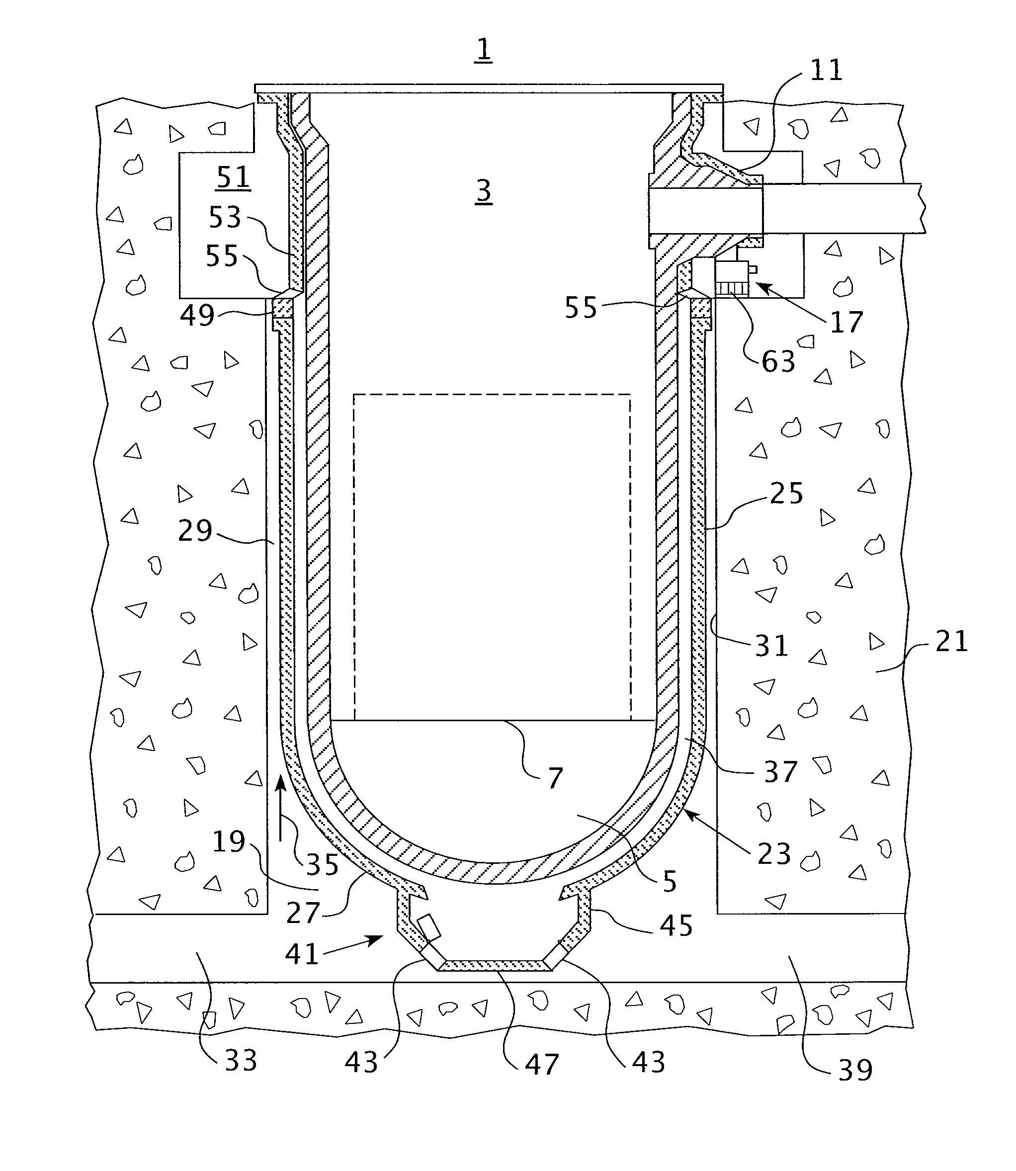
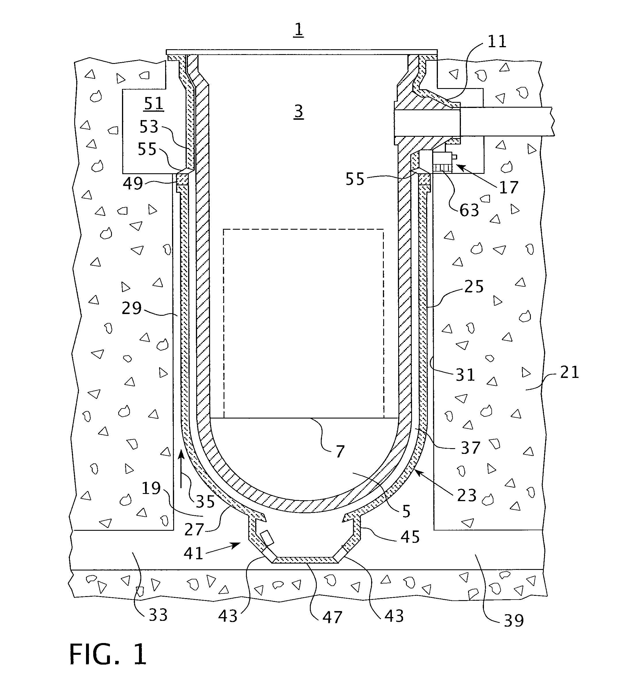
[0023]FIG. 1 illustrates the pertinent portions of a nuclear reactor installation 1 in the form of an advanced pressurized water reactor. The reactor includes an upright cylindrical vessel 3 having a hemispherical lower end 5. The reactor vessel 3 contains a core 7 of fissionable material. As is well known, reactor fluid in the form of light water is circulated through the core. The hot coolant is discharged through hot leg nozzles 9 (shown in FIG. 2) for circulation through a steam generator (not shown) which utilizes the heat m the coolant to generate steam for a turbine generator (also not shown). The coolant is returned to the reactor vessel 3 through cold leg nozzles 1.1. The exemplary plant is a two-loop installation; thai is, the single reactor supplies heated coolant for two steam generators. As illustrated in FIG. 2, each loop includes one hot leg 13 connected to a hot leg nozzle 9 aid two coo! legs 15 connected to cold leg nozzles 11. While FIG. 2 only shows the nozzle arr...


PUM


Abstract

The reactor vessel of a nuclear reactor installation which is suspended from the cold leg nozzles in a reactor cavity is provided with a lower thermal insulating barrier spaced from the reactor vessel that has a hemispherical lower section that increases in volume from the center line of the reactor to the outer extent of the diameter of tiie thermal insulating barrier and smoothly transitions up the side walls of the vessel. The space between the thermal insulating harrier and the reactor vessel forms a chamber which can be flooded with cooling water through passive valving to directly cool the reactor vessel in the event of a severe accident. The passive inlet valve for the cooling water includes a buoyant door that is normally maintained sealed under its own weight and floats open when the cavity is Hooded. Passively opening steam vents are also provided.

Description

CROSS-REFERNCE TO RELATED APPLICATIONS [0001]This application claims priority to U.S. Provisional Application serial No. 60 / 890625, filed Feb. 20, 2007.GOVERNMENT INTEREST [0002]This invention was made with government support under Contract No. DE- FC07-05ID14636, awarded by the Department of Energy. The government has certain rights in this invention.BACKGRON OF THE INVENTION [0003]1. Field of the Invention[0004]This invention relates to an apparatus for providing thermal insulation around a nuclear reactor pressure vessel while at the same time permitting the reactor vessel to be surrounded passively with cooling water in the event of a severe accident in which the core material relocates.[0005]2. Background Information[0006]The pressure vessel of a nuclear reactor that houses the nuclear fuel must he provided with biological shielding to protect personnel and equipment in the surrounding area from the high neutron flux and radiation produced by the fission reactions within the co...

Claims


Application Information

Patent Timeline
Patent Type & Authority Applications(United States)
IPC IPC(8): G21C11/00
CPCG21C11/08G21C15/18Y02E30/40G21Y2002/207G21Y2004/30G21Y2002/201Y02E30/30
Inventor KEEGAN, C. PATRICKSCOBEL, JAMES H.WRIGHT, RICHARD F.
Owner WESTINGHOUSE ELECTRIC CORP
Why Eureka
Try Eureka