Fiber optic cable assembly for optical transceiver

a technology of fiber optic cables and optical transceivers, applied in the field of fiber optic transceivers, can solve the problems of mechanical damage to optical systems, extremely fragile fiber pigtails, and difficulty in adjusting the pigtail, and achieve the effect of reducing the effect of errors

a technology of fiber optic cables and optical transceivers, applied in the field of fiber optic transceivers, can solve the problems of mechanical damage to optical systems, extremely fragile fiber pigtails, and difficulty in adjusting the pigtail, and achieve the effect of reducing the effect of errors

US20080199187A1Inactive Publication Date: 2008-08-21TYCO ELECTRONICS SERVICES GMBH +1

Image

  • Fiber optic cable assembly for optical transceiver
  • Fiber optic cable assembly for optical transceiver
  • Fiber optic cable assembly for optical transceiver

Examples


Embodiment Construction

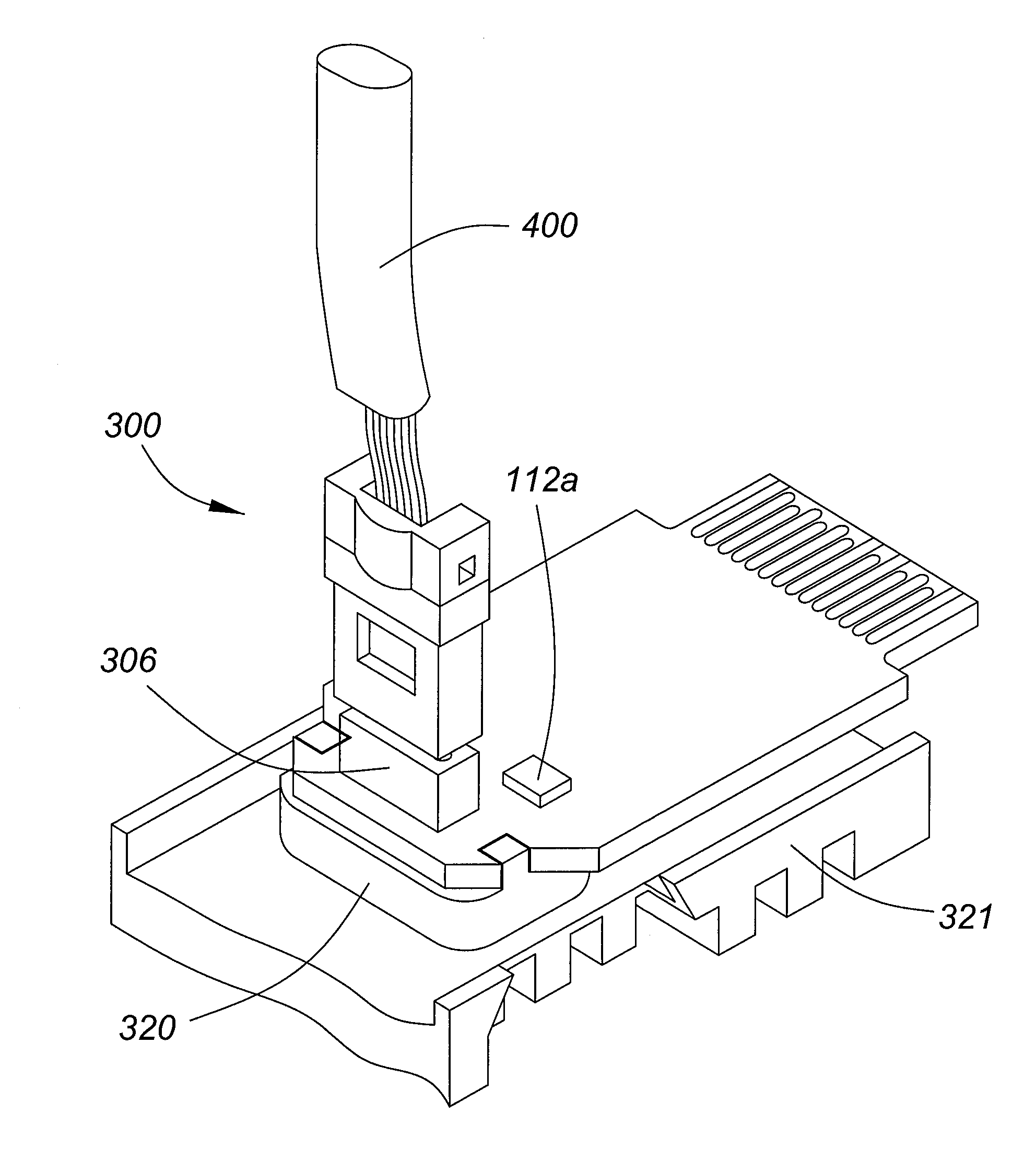
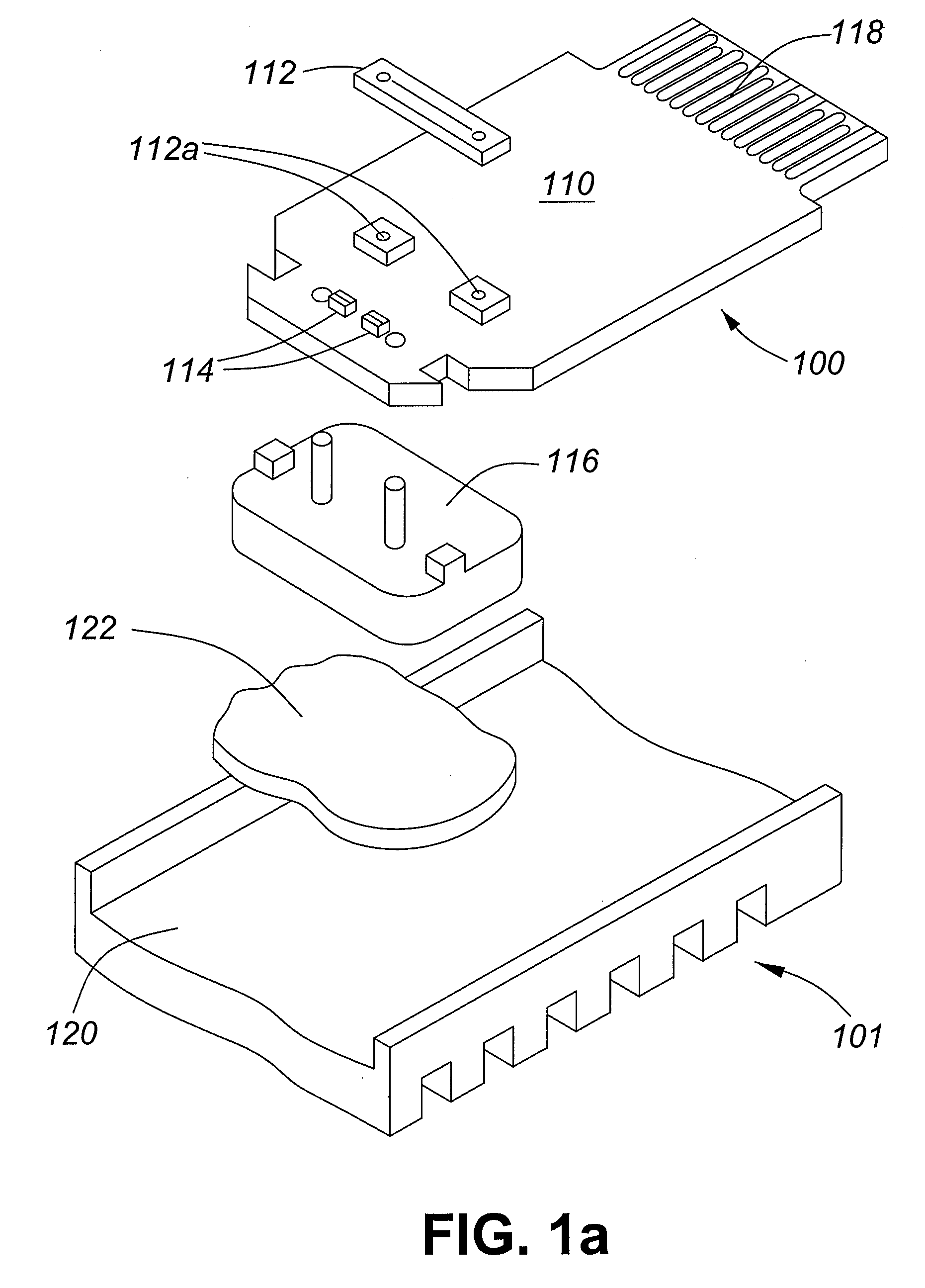
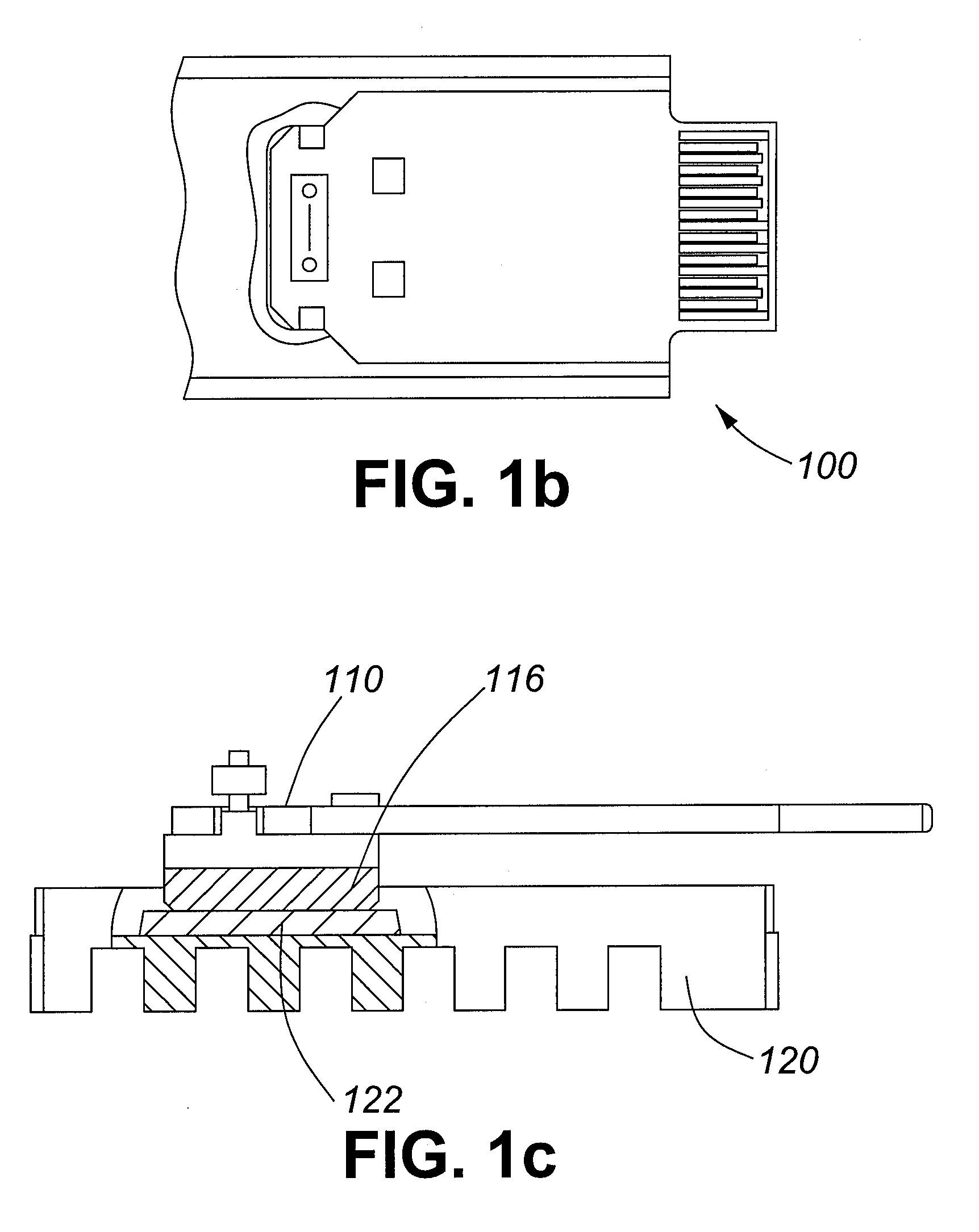
[0036]Referring to FIGS. 1a, 1b and 1c, there is provided optical device 101 in accordance with the teachings of this invention. The optics of the optical device are packaged in a unitary structure referred to herein as the optical sub-assembly 100, in which all optical alignments are contained. The optics may include, for example, lens 112, driver circuitry 112a, and optical die 114.

[0037]The optical sub-assembly 100 is placed on a printed circuit board (PCB) 110. The optics of the optical sub-assembly 100 may be passively aligned to the PCB 110 with use of mechanical features integrated in a heat sink carrier 116, as described in more detail below in conjunction with FIGS. 2a, 2b and 2c. The PCB 110 and mounted optical sub-assembly 100 are then mounted in an external carrier 120. The combination of the optical sub-assembly 100, PCB 110 and external carrier 120 collectively form optical device 101.

[0038]The PCB 110 may further include a male electrical connector 118 mounted thereon...


PUM


Abstract

Disclosed is an optical floating sub-assembly, comprising a thermally conductive non rigid substance between the heat sink carrier and external casing, to minimize mechanical stress on the optical assembly. Also disclosed is a printed circuit board as an electrical interface, comprising two modules capable of converting an electrical signal to an optical signal, transmitting the optical signal and then converting the optical signal back to an electrical signal. Also disclosed is an optical assembly, comprising a heat sink with mechanical features for optical alignment.

Description

CROSS-REFERENCE TO RELATED APPLICATION[0001]This application claims the benefit of U.S. Provisional Application No. 60 / 901,872 filed Feb. 16, 2007, incorporated by reference herein.FIELD OF THE INVENTION[0002]The present invention broadly relates to fiber optic transceiver.BACKGROUND OF THE INVENTION[0003]Various types of optical fiber cable assemblies have been developed since the inception of optical fiber communications systems. Many fiber optic products incorporate fiber pigtail interfaces between the optical device and the optical connector, collectively referred to as cable assemblies. These fiber pigtails are extremely fragile and must be handled carefully. However, optical systems are subject to mechanical stresses which can damage the systems. In particular, the interface between the fiber optic connector and cable is particularly sensitive to damage arising from the concentration of stress at the connector interface and the weight of the connector body. In certain instance...

Claims


Application Information

Patent Timeline
21 Aug 2008
Publication
US20080199187A1
IPC
H04B10/00
CPC
G02B6/4292; G02B6/4249; G02B6/4284
Inventors
ANDERSSON, HANS MAGNUS EMIL; JOHANSSON, ASA CHRISTINA