Drilling tool

Active Publication Date: 2008-08-21
KENNAMETAL INC
View PDF23 Cites 46 Cited by
  • Summary
  • Abstract
  • Description
  • Claims
  • Application Information

AI Technical Summary

Benefits of technology

[0013]For the additional stabilization of the clearance cutting edge, in one particular configuration, a cutting edge land is provided between the clearance cutting edge and the clearance cutting edge/minor cutting edge. This edge land can be realized or substantially realized in the form of a single land or a double land. A cutting edge land of this type promotes or essentially promotes the removal of the chip and thus contributes or substantially contributes to reducing or substantially reducing the chattering tendency on one hand and to reducing or substantially reducing the risk of the drill jamming in the boring during the drilling process on the other hand. The cutting edge lands located both in the vicinity of the cutting corners of the clearance cutting edge as well as in the vicinity of the nose of the guide cutting edge stabilize or essentially stabilize the true or substantially true running of the drill and lead to an elongation of the active cutting edge. They further promote the build-up of an abrasive edge. Finally, they promote or essentially promote the upward removal of the chip, which in turn leads to an undamaged or essentially or substantially undamaged boring wall.
[0014]Providing a cutting edge corner radius in the vicinity of the noses of the guide cutting edge on one hand and of the clearance cutting edge on the other hand. This measure also promotes or substantially promotes the desired smooth or essentially smooth runni

Problems solved by technology

This document also describes the problem known in the technical literature as “chatter”, a problem that is experienced with drill during the drilling process when the irregular rotational action of the drill during the drilling process results in an irregular surface structure of the boring wall.
This symmetrical distribution has the further disadvantage that the vibrations of the drill that cause the “chatter” recur periodically during the drilling process.
This periodic recurrence of the vibrations causes an increas

Method used


Image

  • Drilling tool
  • Drilling tool
  • Drilling tool

Examples


Embodiment Construction

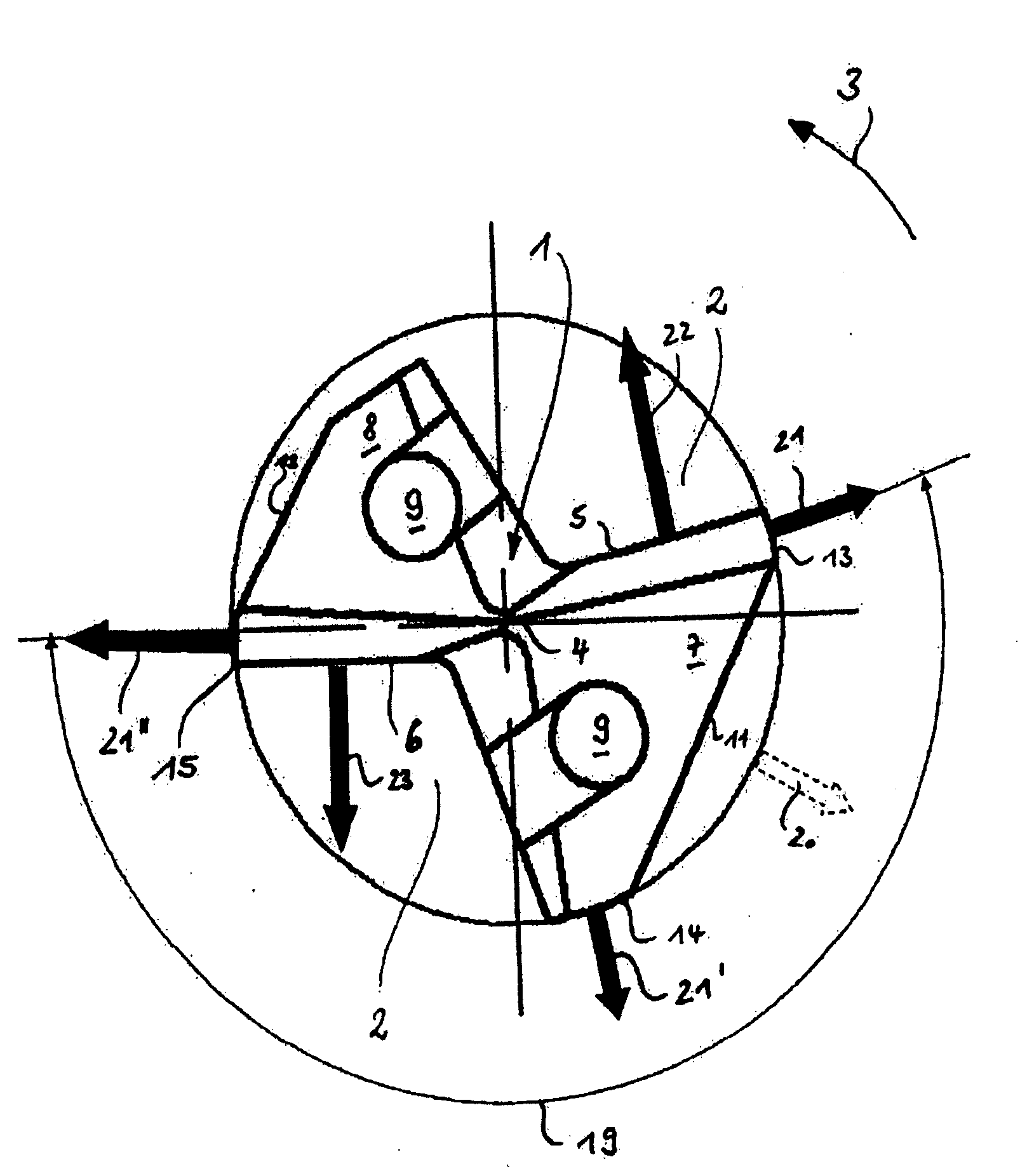
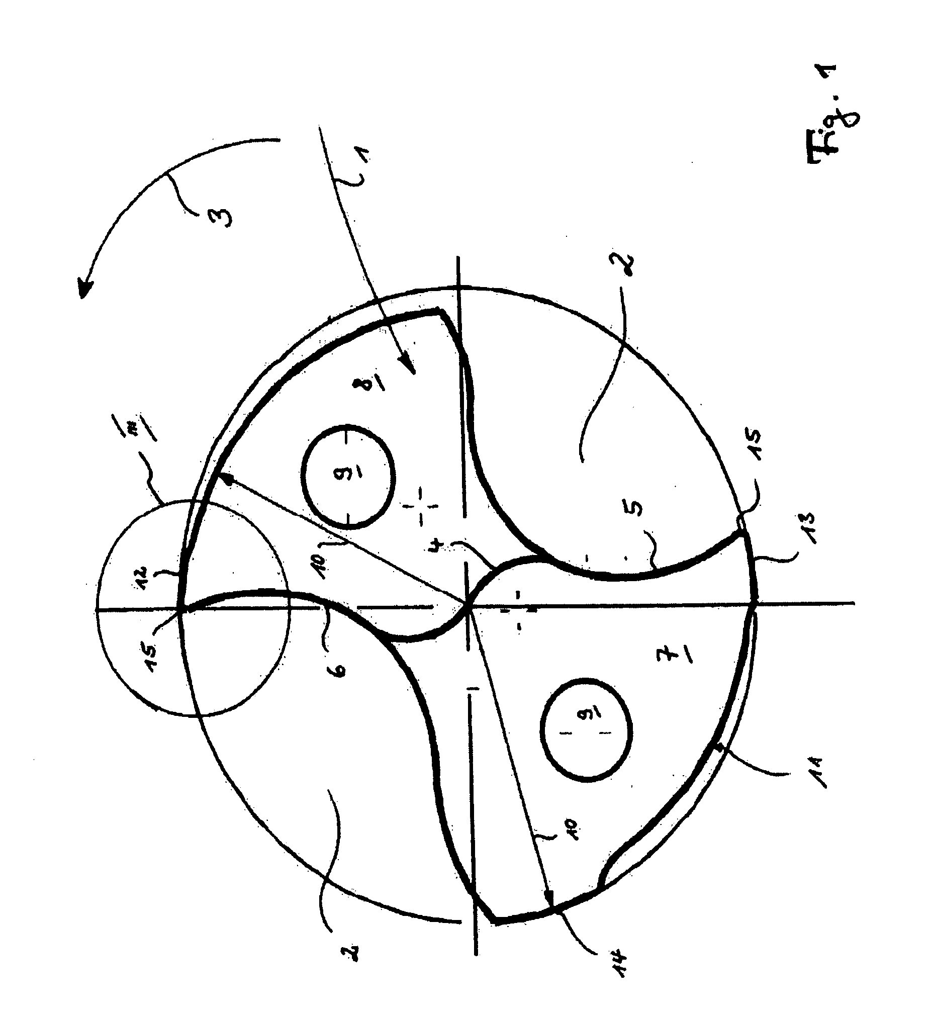
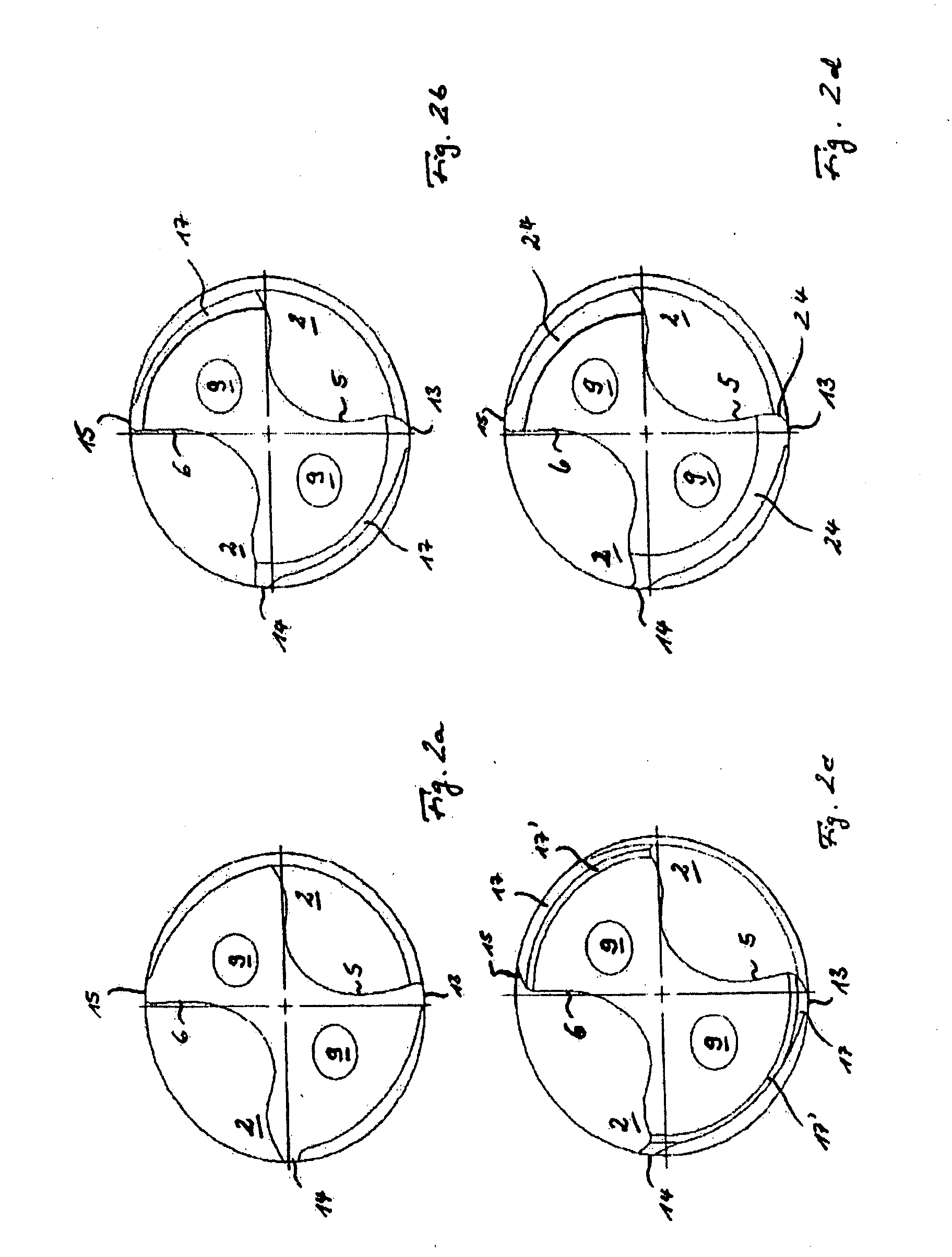
[0028]The drill illustrated in the accompanying figures has a basic or substantially basic shape that has a hollow cylindrical cross section or substantially hollow cylindrical cross section, and consists of a drill core 1 and two chip flutes 2 worked into the drill core 2. During the drilling process, the drill rotates or essentially rotates in the direction of rotation 3. During the drilling, the cutting is done or essentially done by the chisel edge 4, the guide edge 5 and the clearance cutting edge 6 which are shown or essentially shown on the end surface of the drill in the figures. The chisel edge 4, the guide edge 5 and the clearance cutting edge 6 form or substantially form the major cutting edge of the drill, whereby the chisel edge 4 divides or substantially divides this major cutting edge in two parts. The chisel edge 4—if desired—can also be pointed or substantially pointed.

[0029]The two partial cutting edges 5, 6 that extend or substantially extend the chisel edge 4 to ...


PUM

PropertyMeasurementUnit
Angleaaaaaaaaaa
Angleaaaaaaaaaa
Lengthaaaaaaaaaa

Abstract

A drilling tool. The abstract of the disclosure is submitted herewith as required by 37 C.F.R. §1.72(b). As stated in 37 C.F.R. §1.72(b): A brief abstract of the technical disclosure in the specification must commence on a separate sheet, preferably following the claims, under the heading “Abstract of the Disclosure.” The purpose of the abstract is to enable the Patent and Trademark Office and the public generally to determine quickly from a cursory inspection the nature and gist of the technical disclosure. The abstract shall not be used for interpreting the scope of the claims. Therefore, any statements made relating to the abstract are not intended to limit the claims in any manner and should not be interpreted as limiting the claims in any manner.

Description

BACKGROUND[0001]1. Technical Field[0002]This application relates to a drill for use in a machine tool with a major cutting edge divided into two partial cutting edges by a chisel edge (4), one partial cutting edge of which is a guide cutting edge (5) with a guide land (13) on its end farther from the chisel edge (4) in the radial direction (10), and with a support land (14) on the guide cutting edge / minor clearance face (11) associated with the guide cutting edge (5), such that the support land (14) and the guide land (13) between them form the boundaries of the guide cutting edge / minor clearance face (11) in the direction of rotation (3) of the drill.[0003]2. Background Information[0004]An example of a drill of this type is shown in EP-B-290 520 (Corresponding to U.S. Pat. No. 4,913,603), for example. This document also describes the problem known in the technical literature as “chatter”, a problem that is experienced with drill during the drilling process when the irregular rotati...

Claims


Application Information

Patent Timeline
IPC IPC(8): B23B51/02
CPCB23B51/02B23B2251/14B23B2251/245B23B2251/282Y10T408/9097B23B2251/44B23B2251/70Y10T408/909B23B2251/406
Inventor KRENZER, ULRICH F.KAUPER, HERBERT R.
Owner KENNAMETAL INC
Why Eureka
Try Eureka