
Mixer with self-calibrating carrier leakage mechanism

a self-calibrating, carrier technology, applied in the field of mixers, can solve the problems of reducing the performance of the mixer, q gain/phase imbalance must be overcome, and the difficulty of complete elimination

Active Publication Date: 2008-08-21
MEDIATEK INC
View PDF12 Cites 10 Cited by
  • Summary
  • Abstract
  • Description
  • Claims
  • Application Information

AI Technical Summary

Problems solved by technology

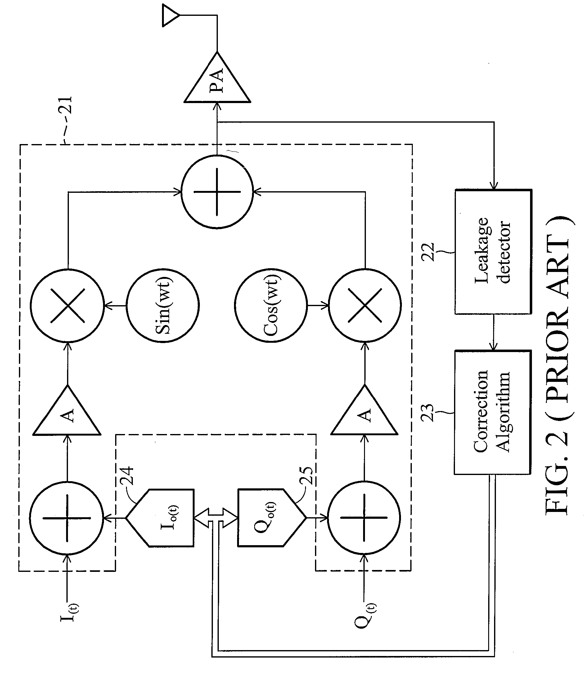
In direct conversion transmitters, however, LO pulling, RF carrier leakage due to I-Q DC offset, and I-Q gain / phase imbalance problems must be overcome.
But, in real practice, complete elimination is difficult to achieve.
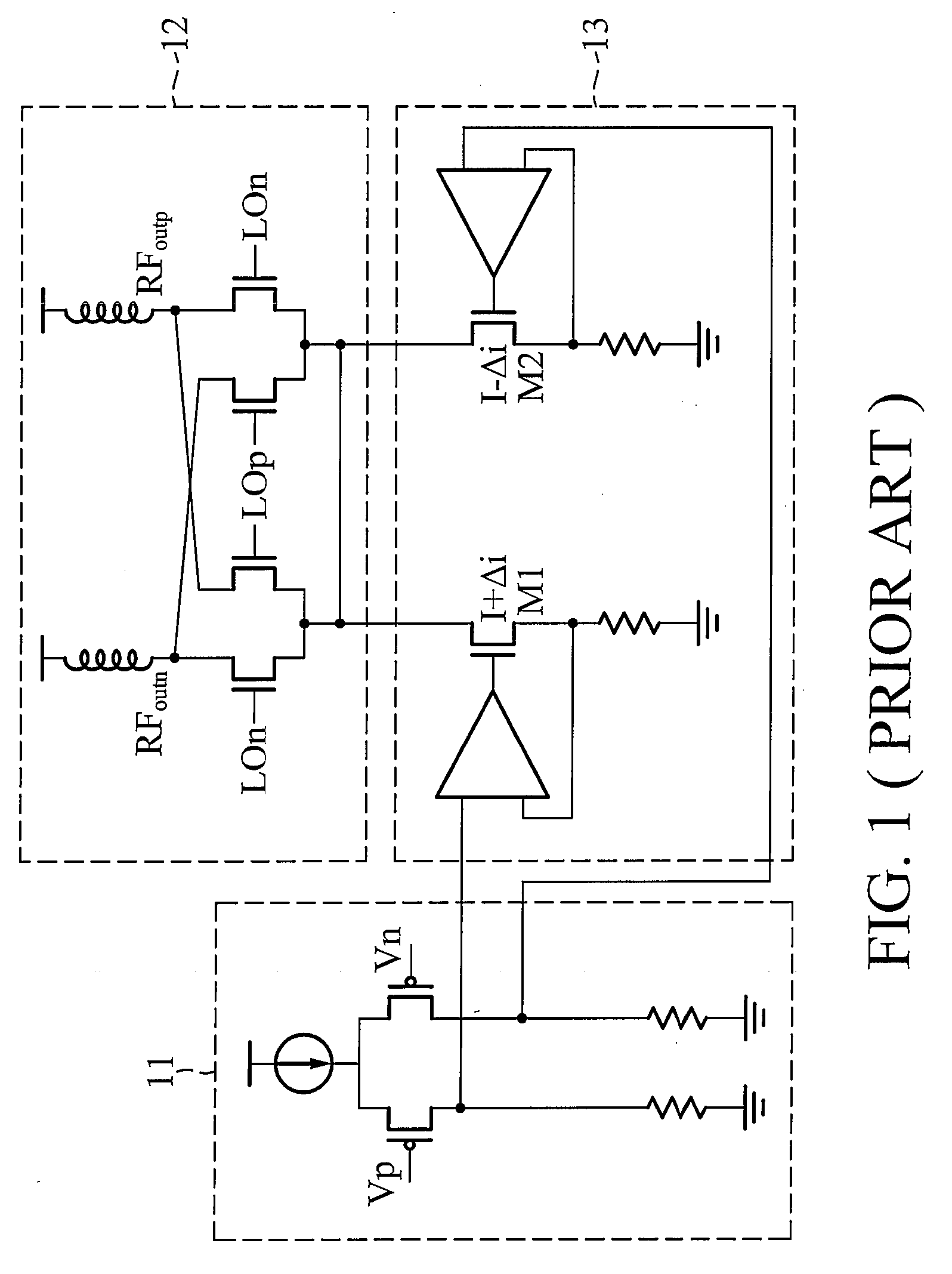
The unwanted carrier power, referred to as local oscillator leakage, reduces the performance of the mixer 12.

Method used


Image

  • Mixer with self-calibrating carrier leakage mechanism
  • Mixer with self-calibrating carrier leakage mechanism
  • Mixer with self-calibrating carrier leakage mechanism

Examples


Embodiment Construction

[0025]The following description is of the best-contemplated mode of carrying out the invention. This description is made for the purpose of illustrating the general principles of the invention and should not be taken in a limiting sense. The scope of the invention is best determined by reference to the appended claims.

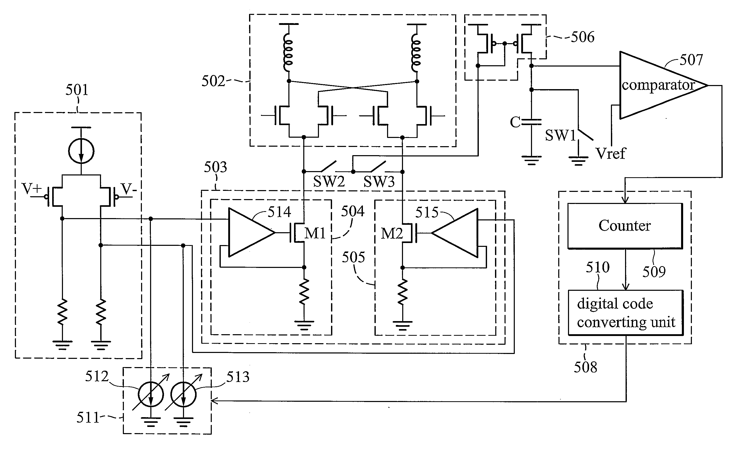
[0026]FIG. 4 is a block diagram illustrating an embodiment of a mixer with carrier leakage calibrating mechanism. The input stage 401 generates and transmits a pair of differential signals to the gm stage 403. The gm stage 403 is further coupled to a double balanced mixer 402 (or called switching stage). The gm stage comprises a first processing unit 404 and a second processing unit 405. The double balanced mixer 402 is turned off in response to the carrier leakage calibrating mechanism works. The current duplicating circuit 406 duplicates a first current from the first processing unit 404 or a second current from the second processing unit 405 to charge the capacitor ...


PUM


Abstract

An embodiment of a mixer with carrier leakage self-calibrating is disclosed. The mixer comprises a double balanced mixer, a gm stage comprising a first processing unit and a second processing unit, a current duplicating circuit, a capacitor, a controller and a current compensation unit. The current duplicating circuit selects the first processing unit or the second processing unit and duplicates a duplicated current of the selected processing unit to charge the capacitor. The capacitor has a first terminal and a second terminal, wherein the second terminal is grounded and the first terminal receives the duplicated current. The controller determines a charge time of the capacitor to generate a compensation signal, wherein the charge time is the time that the voltage of the capacitor is charged to equal to a reference voltage. The current compensation unit receives the compensation signal to generate a compensation current to the mixer.

Description

BACKGROUND OF THE INVENTION[0001]1. Field of the Invention[0002]The invention relates to a mixer and more particularly to a mixer with a self-calibrating carrier leakage mechanism.[0003]2. Description of the Related Art[0004]Wireless communication has been widely applied in various applications. Typically, each wireless communication device requires a radio transceiver (i.e., a receiver and a transmitter). With the demand for enhanced performance, a direct conversion technology has been developed for size, cost and lower power consumption. In direct conversion transmitters, however, LO pulling, RF carrier leakage due to I-Q DC offset, and I-Q gain / phase imbalance problems must be overcome.[0005]FIG. 1 is a circuit diagram illustrating the leakage current effect on the modulator outputs. Input stage 11 provides two differential input signals, Vp and Vn, to the gm stage 13. The local oscillator generates two differential signals at a carrier frequency. During the direct conversion mod...

Claims


Application Information

Patent Timeline
Patent Type & Authority Applications(United States)
IPC IPC(8): H04B1/00
CPCH03D7/1441H03D2200/009H03D2200/0033H03D7/1458
Inventor CHUNG, YUAN-HUNG
Owner MEDIATEK INC
Learn More