Forward and rearward motion switching mechanism using brake band

a technology of forward and rearward motion and switching mechanism, which is applied in the direction of toothed gearings, belts/chains/gearrings, and toothed gearings, etc., can solve the problems that disc brakes have adverse influence on the efficiency of cvt, and achieve the effects of reducing fuel expenses, reducing drag torque, and reducing power loss

Inactive Publication Date: 2008-08-21
NSK WARNER
View PDF7 Cites 8 Cited by
  • Summary
  • Abstract
  • Description
  • Claims
  • Application Information

AI Technical Summary

Benefits of technology

[0021]With a forward and rearward motion switching device according to the present invention, it is possible to reduce a drag torque approximately by half, compared with a wet type multiple disc brake having the same capacity. Since capable of thus reducing a power loss, if used as a brake of a forward and rearward motion switching device of an automatic transmission, this arrangement can contribute to reduce fuel expenses. Particularly when this device is used in a vehicle employing a continuously variable transmission, higher efficiency of the continuously variable transmission can be achieved, to thereby greatly contribute fuel efficiency.

Problems solved by technology

However, in the forward and rearward motion switching device, the element to be fixed of the planetary gear mechanism is always rotating even when the engine is in rotation and the brake is not applied.
For this reason, when a wet type multiple disc brake is used in the planetary gear mechanism of the forward and rearward motion switching device, a drag torque between a friction disc and a separator disc of the wet type multiple disc brake gives adverse influence on the efficiency of the CVT.

Method used


Image

  • Forward and rearward motion switching mechanism using brake band
  • Forward and rearward motion switching mechanism using brake band
  • Forward and rearward motion switching mechanism using brake band

Examples


first embodiment

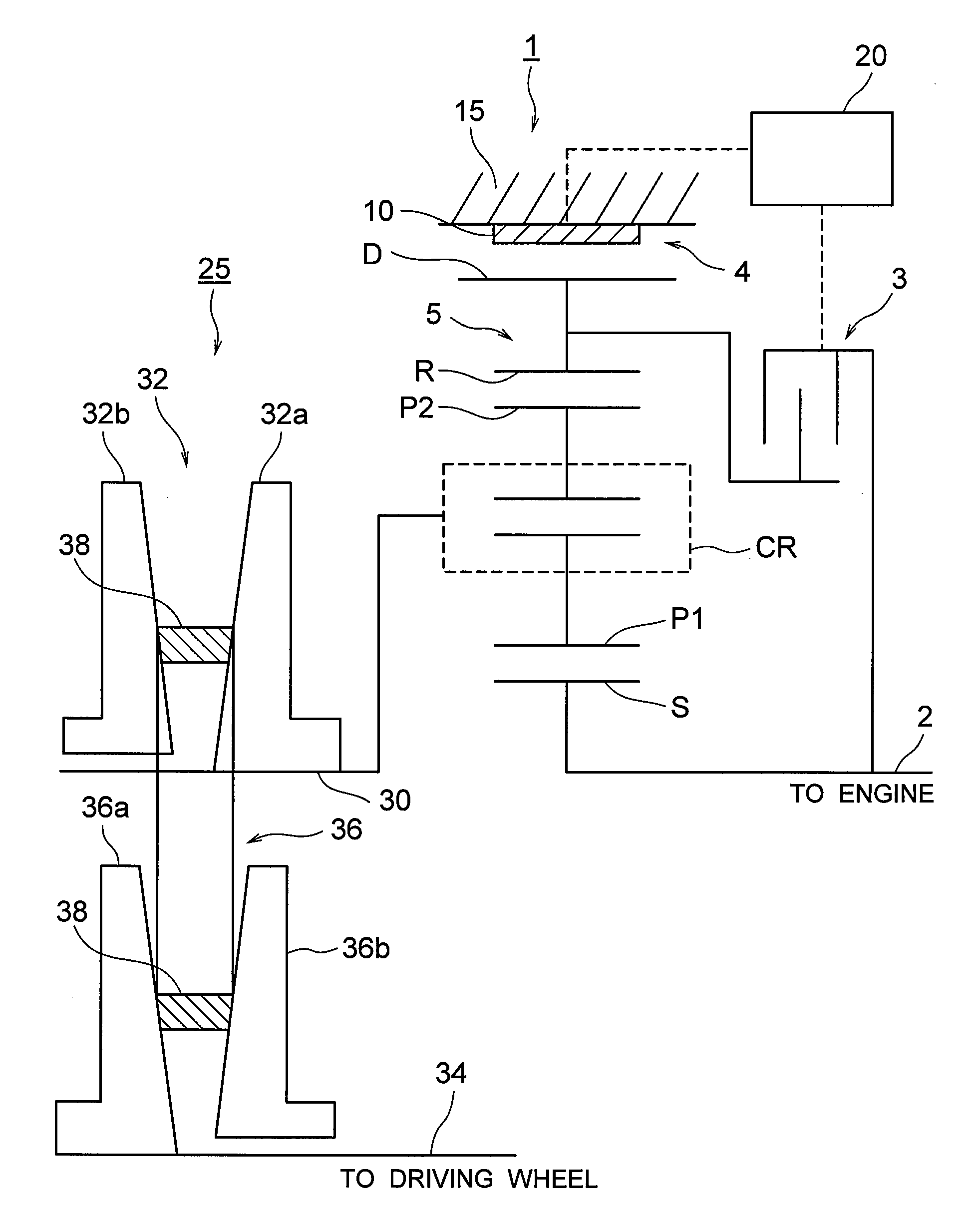
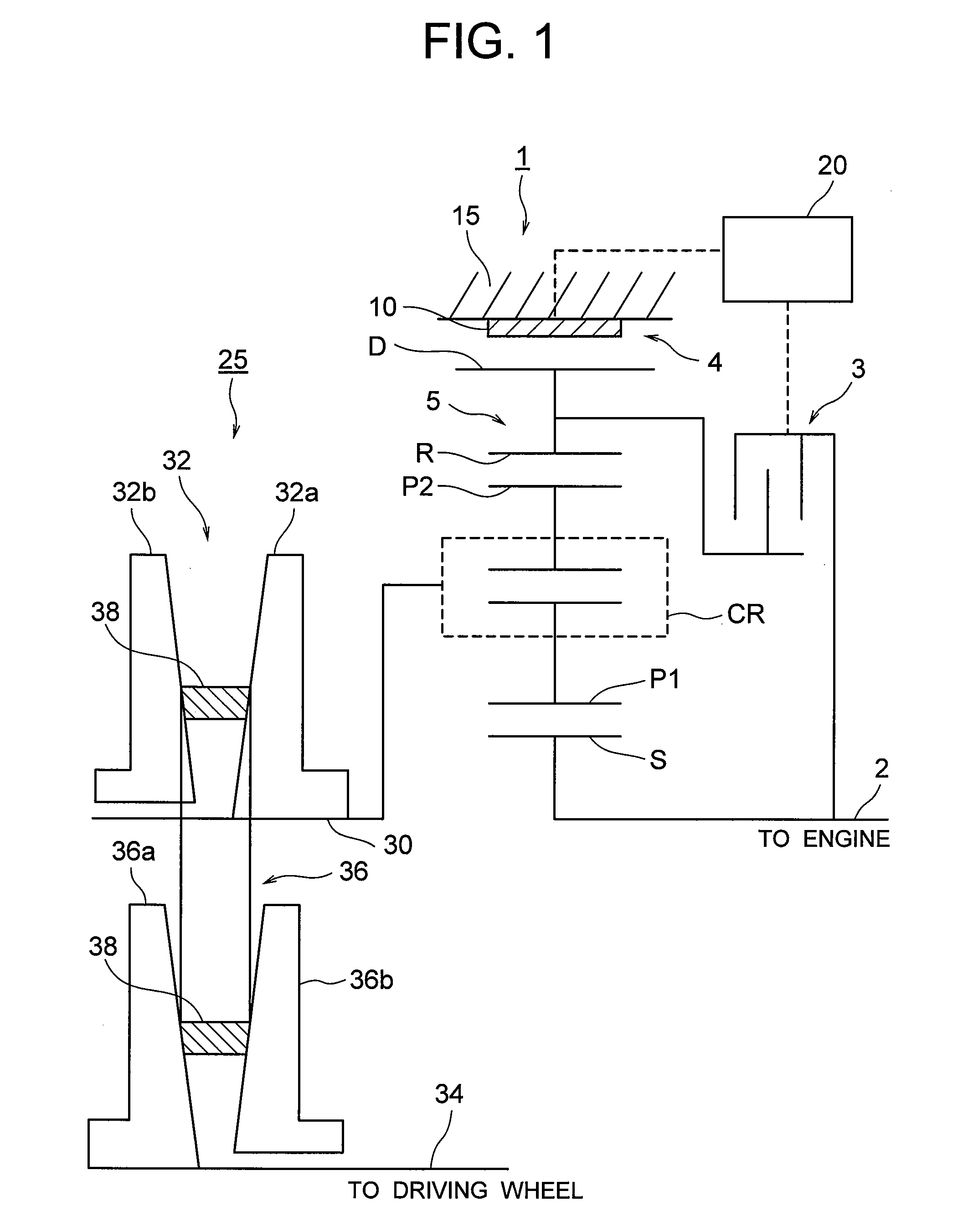
[0041]In the present embodiment, in a forward running of the vehicle, the clutch 3 is engaged through the control device 20, and a rotational driving force of the engine which is transmitted to the input shaft 2 through an unillustrated torque converter is transmitted to the sun gear S and the planetary carrier CR, whereby the sun gear S and the planetary carrier CR are integrally rotated in the same direction as the rotation of the input shaft 2. Upon the integral rotation of the sun gear S and the planetary carrier CR, the ring gear R is also integrally rotated in the same direction through the pinion gear P. That is, the sun gear S, the planetary gear CR and the ring gear R are integrally rotated in the same direction as the rotation of the input shaft 2, so that a rotation of the input shaft 2 is transmitted as it is to the primary shaft 30 of the continuously variable transmission 25 which is integrally coupled to the ring gear R. The rotational driving force in the same direct...

second embodiment

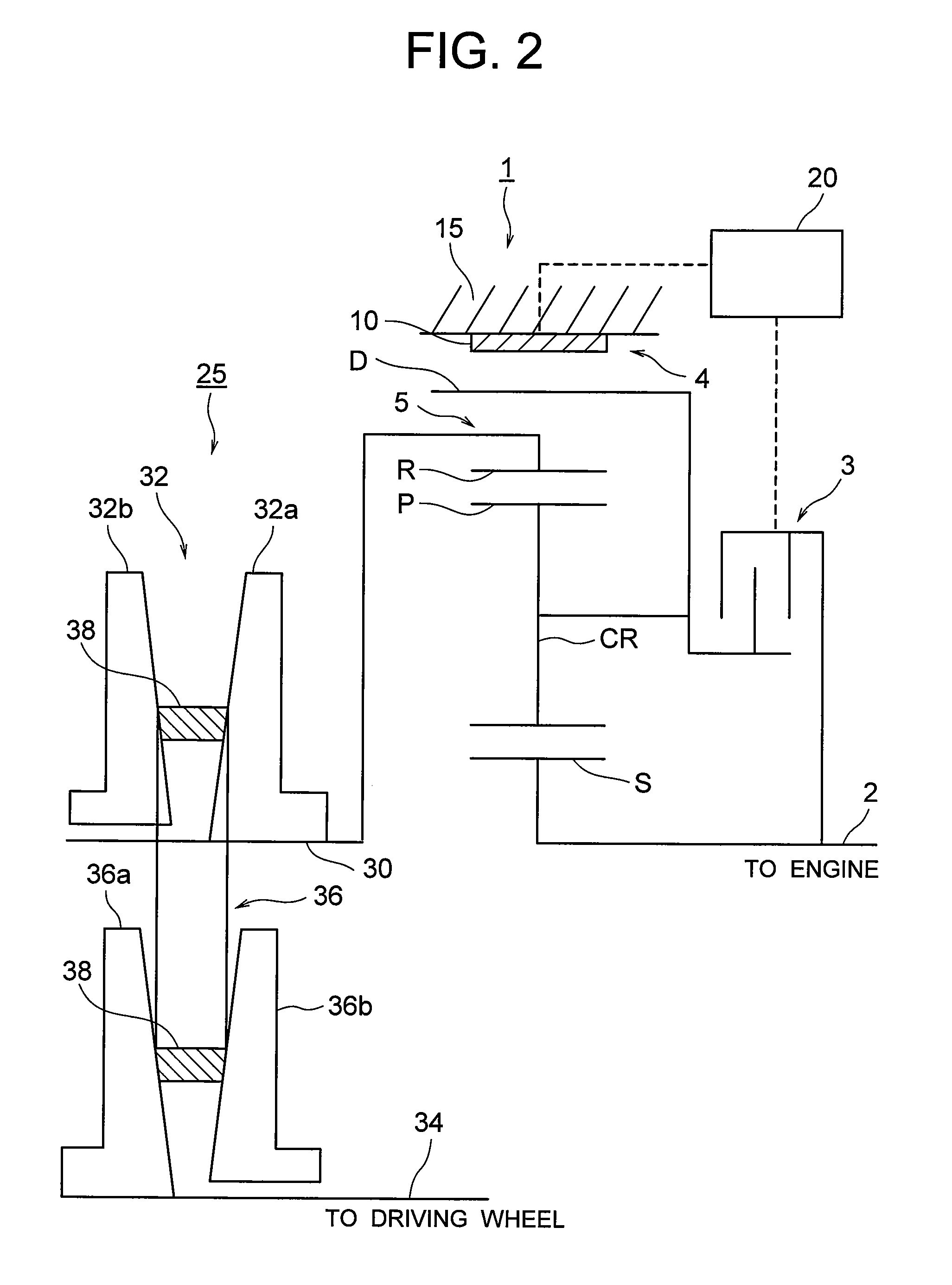
[0045]In the present variation, in forward running of the vehicle, the clutch 3 is engaged through the control device 20, and a rotation of the engine which is transmitted to the input shaft 2 through the torque converter is transmitted to the ring gear R and the planetary carrier CR, whereby the ring gear R and the planetary carrier CR are integrally rotated in the same direction as the rotation of the input shaft 2. Upon the integral rotation of the ring gear R and the planetary carrier CR, the sun gear S is also integrally rotated in the same direction as the rotation of the input shaft 2 through the pinion gear P. That is, the sun gear S, the planetary gear CR and the ring gear R are integrally rotated in the same direction as the rotation of the input shaft 2, so that the rotation of the input shaft 2 is transmitted as it is to the primary shaft 30 of the continuously variable transmission 25 which is integrally coupled to the sun gear S. The rotational driving force in the sam...


PUM


Abstract

A forward and rearward motion switching device to be used in an automatic transmission system for a vehicle, comprises a planetary mechanism provided with an input element, an element to be fixed and an output element which are disposed coaxially and are rotatable relative to each other, the planetary mechanism outputting a rotational driving force of an internal combustion engine transmitted to the input element as a rotational driving force in the reverse direction to the rotation of the input element from the output element through the input element, the element to be fixed and the output element, and a brake capable of fixing the element to be fixed of the planetary mechanism. The brake comprises a rotational drum which is integrally formed with the element to be fixed and has an outer peripheral surface, and a brake band that surrounds the outer peripheral surface of the rotational drum to fix the same.

Description

[0001]This application claims the benefit of Japanese Patent Application No. 2007-035374 which is hereby incorporated by reference.BACKGROUND OF THE INVENTION[0002]1. Field of the Invention[0003]The present invention relates to a forward and rearward motion switching mechanism of an automatic transmission for a vehicle.[0004]2. Related Background Art[0005]An automatic transmission of a vehicle is equipped, between an input shaft connected to a torque converter and an output shaft, with a forward and rearward motion switching device and an automatic transmission device. The forward and rearward motion switching device and the automatic transmission device are constituted by a plurality of braking mechanisms, a plurality of clutch mechanisms and a plurality of planetary gear mechanisms together in combination. In the planetary gear mechanism, a sun gear having a small diameter and external teeth and a ring gear having a large diameter and internal teeth are provided coaxially and a pi...

Claims


Application Information

Patent Timeline
Patent Type & Authority Applications(United States)
IPC IPC(8): F16H3/44
CPCF16H37/027
Inventor SUZUKI, MORIYA
Owner NSK WARNER
Why Eureka
Try Eureka