

Manufacturing Method for Rotary Electric Machine and Stator
a technology of rotary electric machines and stators, applied in the direction of electrical apparatus, dynamo-electric machines, applying solid insulation, etc., can solve the problems of increasing the number of welding operations, and achieve the effect of enhancing the productivity of welding operations
- Summary
- Abstract
- Description
- Claims
- Application Information
AI Technical Summary
Benefits of technology
Problems solved by technology
Method used
Image

Examples
first embodiment
of the Invention
[0108]A manufacturing method of a rotary electric machine according to a first embodiment of the present invention will now be described with reference to FIGS. 14-29. A method for inserting coils in stator slots, which is one feature of this embodiment, will be described.
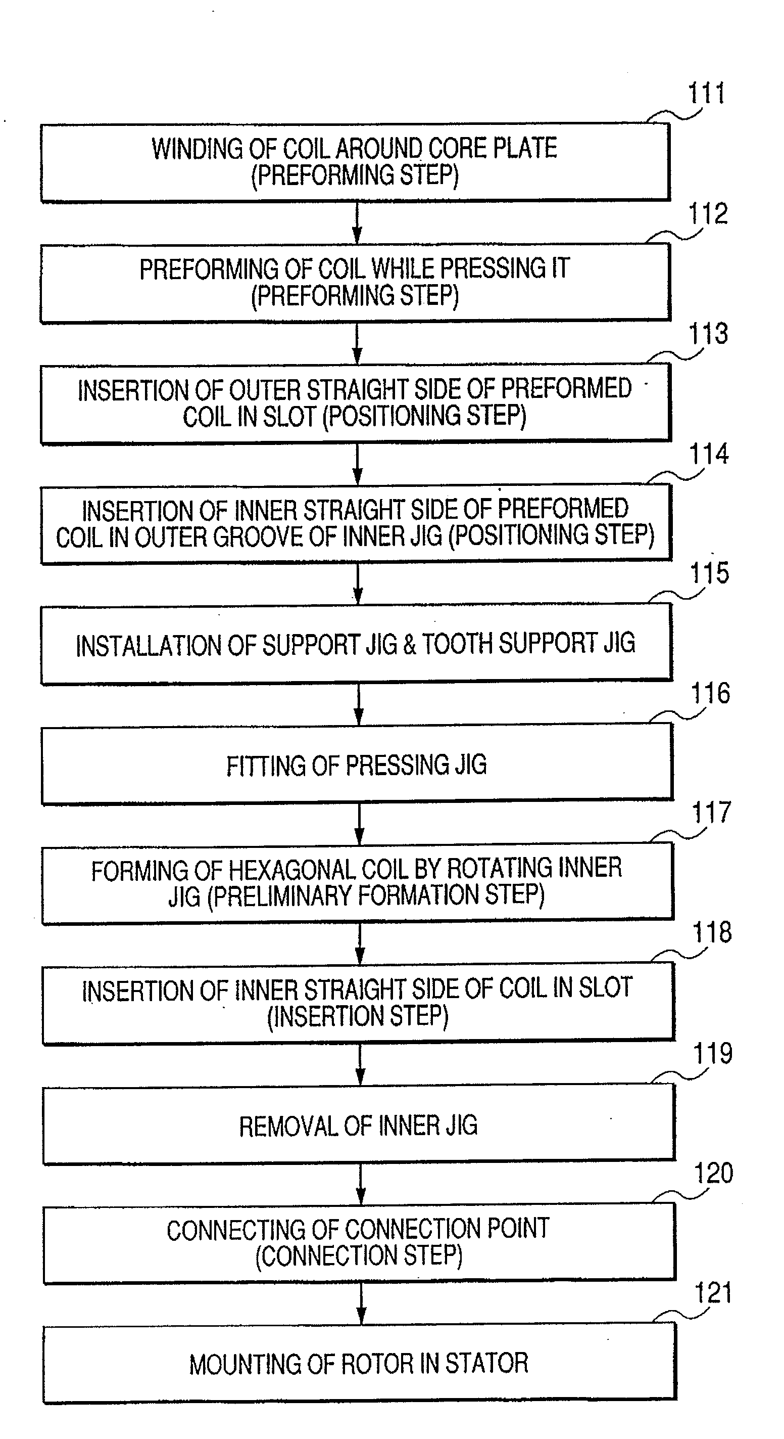
[0109]FIG. 14 is a flow chart for explaining an example of manufacturing steps according to a first embodiment of the present invention. FIGS. 15(a) and 15(b) are schematic illustrations for explaining a method for forming oval shaped element coils, according to the first embodiment. FIG. 15(a) is a perspective view of a stator coil wound around a core plate; and FIG. 15(b) is an enlarged view of the encircled part (b) in FIG. 15(a). In the manufacturing method of this embodiment, a step 111 of the FIG. 14 flow chart firstly winds an insulated conductor such as an enamel wire around a core plate 14 several turns to form element coils 4131a and 4131b. As shown in FIG. 15(a), the core plate 14 is a th...
second embodiment
of the Invention
[0153]A manufacturing method of a rotary electric machine according to a second embodiment of the present invention will now be described with reference to FIGS. 30-32. FIG. 30 is a simplified schematic illustration for explaining a manner in which a pair of element coils is wound according to the second embodiment. FIGS. 31(a) and 31(b) are schematic illustrations for explaining a preforming method of a stator coil, according to the second embodiment. Here, FIG. 31(a) is a top view in which the preforming operation is performed, while FIG. 31(b) is an illustration viewed from the direction of arrow A in FIG. 31(a). FIG. 32 is a schematic illustration showing a perspective view of a stator coil formed by using the preforming method of the second embodiment. Parts identical to those of the first embodiment are indicated by the same names and the same reference numerals.
[0154]The first and second embodiments differ in the manner in which a pair of element coils 4131a a...
third embodiment
of the Invention
[0165]Next, a manufacturing method of a rotary electric machine according to a third embodiment of the present invention will be described with reference to FIGS. 33-41. Parts common to the other aforementioned embodiments are indicated by the same names and the same reference numerals.
[0166]This embodiment differs from the second embodiment in the positioning step through the insertion step, but the other steps are similar therebetween. Therefore, only the positioning step through the insertion step of this embodiment will be described.
[0167]FIG. 33 is a manufacturing flow chart for explaining a positioning step through an insertion step, which is a feature of the third embodiment. FIG. 34 is a schematic illustration showing a perspective view of a preformed coil fitted in a slide jig used in the third embodiment. FIG. 35 is a schematic illustration showing a perspective view in which the slide jig is slid to form element coils in a substantially hexagonal shape. Th...
PUM
 Abstract
Description
Claims
Application Information