Backup power system

a power system and back-up technology, applied in the direction of emergency power supply arrangements, transportation and packaging, sustainable buildings, etc., can solve the problems of increasing conversion losses, unable to ensure current supply to the associated loads, and undesirable other sides, etc., to achieve optimal adaptation to increasing power needs, low cost, and high current intensities

Active Publication Date: 2008-08-28
SMA SOLAR TECH AG
View PDF15 Cites 83 Cited by
  • Summary
  • Abstract
  • Description
  • Claims
  • Application Information

AI Technical Summary

Benefits of technology

[0039]The invention further provides an online UPS system, it being advantageous if the switching time of each switch is no more than 50 ms, more specifically no more than 30 ms; each switch may thereby be implemented as a contactor. Secure uninterruptible power supply is thus ensured.
[0053]The additional device further comprises an automatic disconnection switch, a transfer contactor, a contactor, a grid voltage meter and a grid current meter, so that the device can be operated self-sufficiently.

Problems solved by technology

In the event of a failure of the utility grid, electric loads must be connected by hand to the additional socket, which on the one side is inconvenient and on the other side is also very undesirable in some cases because of the current interruption.
If the online UPS system is defective, the electric loads supplied through the system must be connected to the utility grid via an additional switching device.
This solution does not ensure current supply to the associated loads.
This UPS system has further drawbacks.
If the system is operated as an online UPS system, additional conversion losses must be put up with and a data connection between the existing customer generation systems and the switch unit is also needed.
As a result, it is difficult to convert an existing customer generation system into a system with ensured power supply since the electric loads that are supplied via the online UPS system need to be connected to the utility grid through an additional switching device when the online UPS system is defective.
Accordingly, very big loads cannot be associated with several inverters.
Moreover, the customer generation system, electric loads and the backup power supply are not connected in parallel on the AC side so that a secured power supply of and grid parallel operation is not possible.
As a result, loads consuming high power cannot be associated with several DC-AC converters.
Another disadvantage is that the entire system must be designed for operation as a secured power supply from the onset, when the customer generation system is mounted, since the battery must be connected to the DC side and the DC-AC converter must be also suited for island operation from the very outset.
In addition, existing customer generation systems without DC intermediate circuit, more specifically wind generators with an asynchronous generator, cannot be integrated.
An additional device, namely a bidirectional adapter, is needed and makes the system more expensive.
As a result, the supply of the loads is interrupted in all network configurations.
A disadvantage of this system is hat the customer generation system often turns off in island operation because the grid parameters change more in the island operation mode than in the grid operation mode when loads are added to or removed from the circuit.
As a result, the stability of the entire system is restricted.
Further, modular extension is made more difficult.
When a battery inverter and a customer generation system are coupled to the AC side in accordance with prior art, uninterruptible supply of the loads cannot be achieved because the controller needs to be switched.
Through this switch topology, it is not possible to connect at the same time the solar generator and the battery to the load.
This is expensive since the standalone inverter must be oversized.

Method used


Image

  • Backup power system
  • Backup power system
  • Backup power system

Examples


Embodiment Construction

[0061]In the Figs., the same numerals will be used to identify identical components.

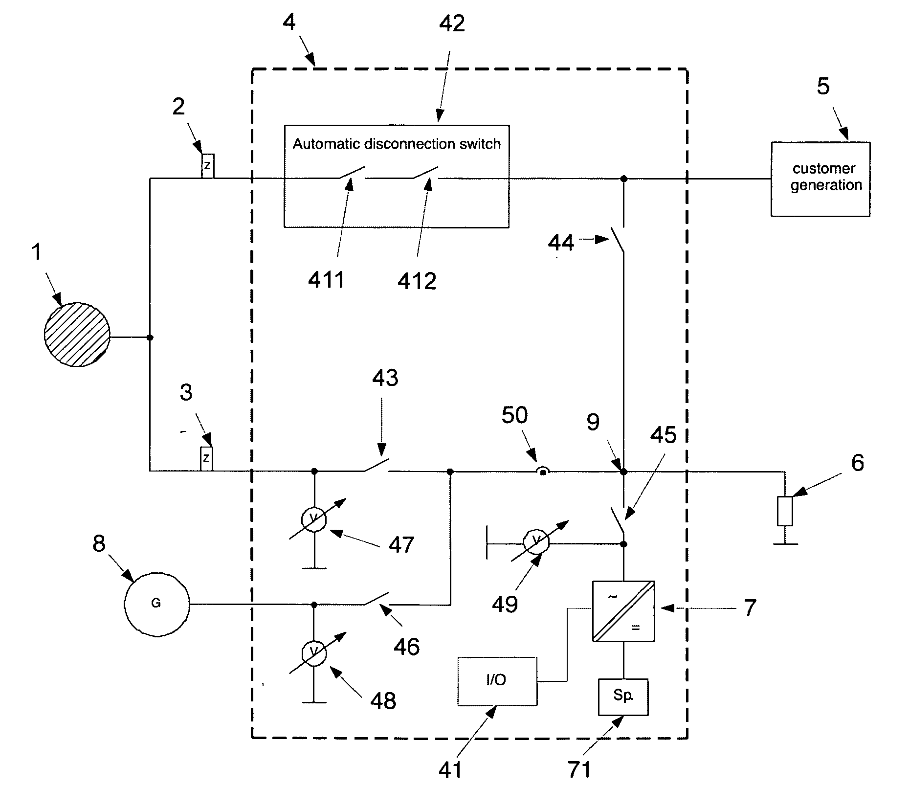
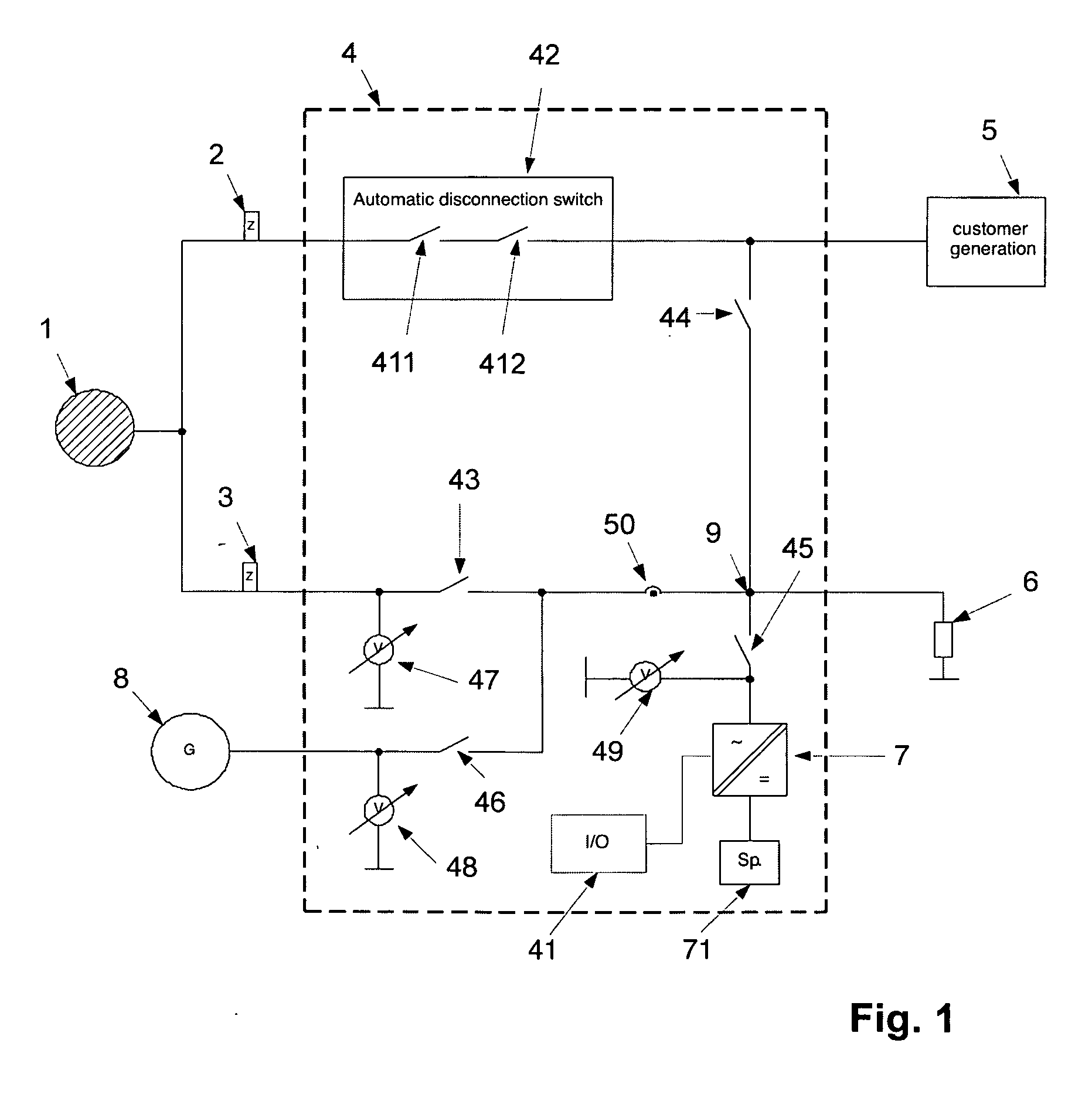
[0062]FIG. 1 depicts an embodiment of a backup power system or additional device 4. This device includes connections for a first meter 2 that is more specifically implemented as a export meter, and a second meter 3, that is more specifically implemented as a import meter.

[0063]The additional device 4 is connected to a utility grid 1 through the export meter 2 and the import meter 3.

[0064]One or several customer generation systems 5 (e.g., solar generator with solar inverter), the loads 6 and at need a generator 8 are connected to the additional device 4 having the standalone inverter 7. The standalone inverter may consist of one or several standalone inverters connected in parallel. The grid monitoring system (ENS) possibly provided in the customer generation system stops operating as soon as the customer generation system 5 has been connected to the additional device 4.

[0065]On its DC side, the stan...


PUM


Abstract

The subject matter of the invention is a backup power system configured to be a UPS system, with a customer generation system (5) and with a network monitoring device with a switch topologya. including a first connection node,a.1 that is connected to the customer generation system (5)a.2 that is connected to at least one automatic disconnection switch including a first switch (411, 412), said first switch (411, 412) being disposed between the customer generation system (5) and a utility grid (1), anda.3 that is connected to a second switch (44) that is connected to one or several loads (6),b. said system including a second connection node (9)b.1 that is connected to said second switch (44)b.2 connected to said load (6),b.3 that is connected to a third switch (43) disposed between the utility grid (1) and the load (6) andb.4 that is connected to a fourth switch (45) to which there is connected a standalone inverter (7) with a storage device (71),c. and said system including a third connection node,c.1 connecting said first switch (411, 412) and said third switch (43) to said utility grid (1),d. said customer generation system (5) supplying an AC voltage that can be added to the circuit, in parallel to said utility grid (1), the grid monitoring device for opening said first switch (411, 412) being provided upon a failure of the utility grid.

Description

CROSS-REFERENCE TO RELATED APPLICATIONS[0001]This application claims Priority from European Application No. EP 07003991.2 filed on 27 Feb. 2007BACKGROUND OF THE INVENTION [0002]The invention relates to a backup power system configured to be a UPS system, with a customer generation system and with a network monitoring device.[0003]Customer generation systems for generating electric energy such as solar generators, wind energy systems with PM generator, variable speed combustion engines or fuel cells the power fed into the grid of which varies strongly are known. Attractive special rates are often offered for such customer generation systems so that, from an economical point of view, it is increasingly interesting for the operator of such systems to feed the generated power into the utility grid. Due to the different rates, the generated and consumed energy is usually metered using different meters. Grid parallel operation calls for taking into consideration particular conditions of s...

Claims


Application Information

Patent Timeline
Patent Type & Authority Applications(United States)
IPC IPC(8): H02J9/00
CPCH02J3/38Y02B10/72H02J9/062H02J3/40Y02B10/70H02J9/06
Inventor KRAMER, THOMASROTHERT, MARTINWACHENFELD, VOLKERFALK, ANDREAS
Owner SMA SOLAR TECH AG
Why Eureka
Try Eureka