LED drive circuit and LED light-emitting device

a technology of led light-emitting devices and drive circuits, which is applied in the direction of electric variable regulation, process and machine control, instruments, etc., can solve the problems of inability to achieve the optimum brightness and emission color of dimming control individually on the different, and the circuit configuration is not easy to perform dimming control. achieve the effect of easy switching color, simplifying circuit configuration, and electrical connection/disconnection with eas

Inactive Publication Date: 2008-08-28
SHARP KK
View PDF7 Cites 125 Cited by
  • Summary
  • Abstract
  • Description
  • Claims
  • Application Information

AI Technical Summary

Benefits of technology

[0020]According to the present invention, the timing with which the secondary side of the switch circuit is brought into/out of conduction is controlled every half wave of alternating-current power from the alternating-current power source. This makes it possible to separately control the amounts of emitted light of the first and second LED groups connected in parallel in such a way as to point in different directions. As a result, in a case where the first and second LED groups are made to emit light of different colors, it is possible to easily change color in a color range covering all the colors obtained by a color combinatio

Problems solved by technology

However, the configurations of Patent Documents 1 and 2 simply aim to achieve a stable driving of LEDs and efficient power consumption, and lacks the circuit configuration for performing dimming control.
As a result, with the configurations of Patent Documents 3 and 4, the circuit configuration increases not only in complexity but also in size.
As a result, although it is possible to continuously change the brightness and emission color at the time of maximum light-emission and the brightness and em

Method used


Image

  • LED drive circuit and LED light-emitting device
  • LED drive circuit and LED light-emitting device
  • LED drive circuit and LED light-emitting device

Examples


first embodiment

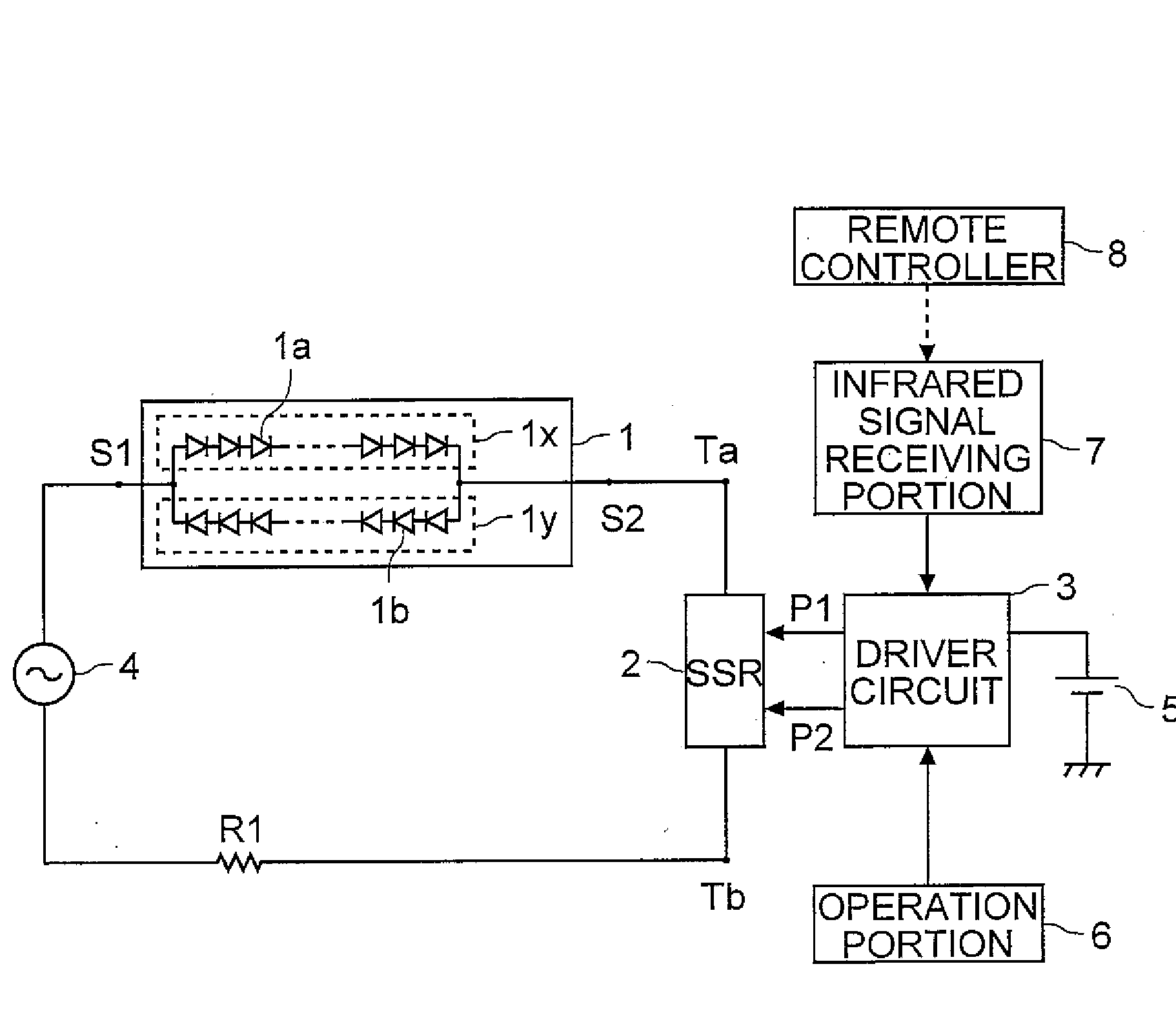
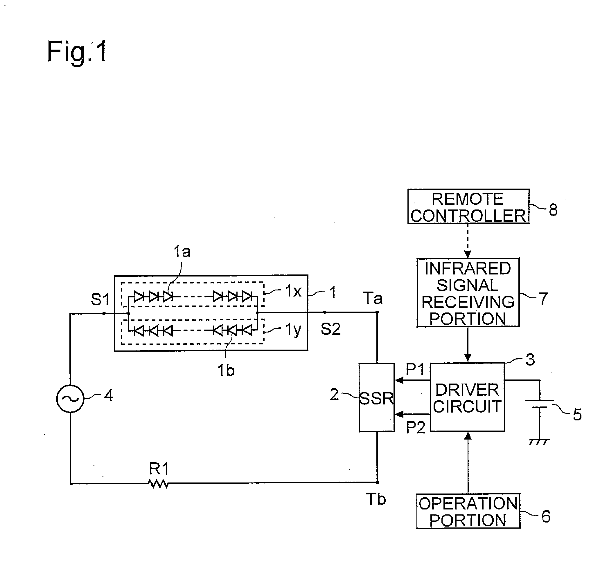
[0139]With reference to the drawings, a first embodiment in which a current passing through the LED unit 1 of the basic configuration described above (FIG. 1) is detected and is then fed back to the driver circuit will be described. FIG. 15 is a block diagram showing a configuration of an LED light-emitting device of this embodiment. In the configuration shown in FIG. 15, such parts and elements as are used for the same purposes as their counterparts in the configuration shown in FIG. 1 are identified with common reference characters, and their detailed descriptions will be omitted.

[0140]The configuration of the LED light-emitting device shown in FIG. 15 is obtained by adding to the configuration shown in FIG. 1 a current detector 11 that detects a current value of the load current by detecting the voltage across the resistor R1. The value detected by the current detector 11 is fed to the driver circuit 3. The driver circuit 3 compares a current value specified by the operation port...

second embodiment

[0151]With reference to the drawings, a second embodiment in which a current passing through the LED unit 1 of the basic configuration described above (FIG. 1) is detected and is then fed back to the driver circuit will be described. FIG. 18 is a block diagram showing a configuration of an LED light-emitting device of this embodiment. In the configuration shown in FIG. 18, such parts and elements as are used for the same purposes as their counterparts in the configuration shown in FIG. 15 are identified with common reference characters, and their detailed descriptions will be omitted.

[0152]The LED light-emitting device shown in FIG. 18 is obtained by adding, to the configuration of the LED light-emitting device shown in FIG. 1, resistors R2x and R2y connected in series to the LED groups 1x and 1y, respectively, of the LED unit 1, and current detectors 11x and 11y for detecting the current value of the load current by detecting the voltages across the resistors R2x and R2y, respectiv...

third embodiment

[0160]With reference to the drawings, a third embodiment in which a color of light emitted from the LED unit 1 of the basic configuration described above (FIG. 1) is detected and is then fed back to the driver circuit will be described. FIG. 20 is a block diagram showing a configuration of an LED light-emitting device of this embodiment. In the configuration shown in FIG. 20, such parts and elements as are used for the same purposes as their counterparts in the configuration shown in FIG. 1 are identified with common reference characters, and their detailed descriptions will be omitted.

[0161]The LED light-emitting device shown in FIG. 20 is obtained by adding, to the configuration of the LED light-emitting device shown in FIG. 1, a color sensor 12 for measuring the color temperature of light emitted from the LED unit 1. A value detected by the color sensor 12 is fed to the driver circuit 3. The driver circuit 3 compares a color according to the color temperature detected by the colo...


PUM


Abstract

A driver circuit 3 feeds a pulse signal to an SSR 2 every half wave of alternating-current power from a commercial power source 4, and thereby separately controls the amounts of emitted light of LED groups 1x and 1y forming an LED unit 1, the LED groups 1x and 1y being connected in parallel in such a way as to point in different directions. That is, a first pulse signal for controlling the duration of light emission of the LED group 1x and a second pulse signal for controlling the duration of light emission of the LED group 1y are fed to the SSR 2 from the driver circuit 3.

Description

[0001]This nonprovisional application claims priority under 35 U.S.C. §119(a) on Patent Application No. 2007-050425 filed in Japan on Feb. 28, 2007, the entire contents of which are hereby incorporated by reference.BACKGROUND OF THE INVENTION[0002]1. Field of the Invention[0003]The present invention relates to LED drive circuits that drive an LED (light-emitting diode) unit, and to LED light-emitting devices provided with such LED drive circuits. More particularly, the present invention relates to an LED drive circuit that drives an LED unit with an alternating-current power, and to an LED light-emitting device provided with such an LED drive circuit.[0004]2. Description of Related Art[0005]In recent years, as increasingly high capacities and hence increasingly high densities have been sought in recording media for recording video and audio data, short-wavelength laser light has been sought after as laser light to be shone onto an optical disc that is a type of recording medium. On ...

Claims


Application Information

Patent Timeline
IPC IPC(8): H05B41/24H05B41/36H05B37/02H01L33/00
CPCH05B33/0815H05B33/0821Y02B20/346H05B33/0869H05B33/0863H05B45/22H05B45/37H05B45/42H05B47/195H05B41/14H05B45/20Y02B20/30
Inventor MARIYAMA, MITSURUOKADA, SEIGO
Owner SHARP KK
Why Eureka
Try Eureka