Inductive Proximity Switch Based on a Transformer Coupling Factor Principle

a technology of coupling factor and proximity switch, which is applied in the direction of coils, magnetic measurements, stray field compensation, etc., can solve the problems of amplitude change, dampening of oscillation circuit, and complex construction, and achieves the effect of reducing the influence of installation damping of proximity switch according to the invention and high weld strength

Active Publication Date: 2008-08-28
PEPPERL FUCHS GMBH
View PDF5 Cites 21 Cited by
  • Summary
  • Abstract
  • Description
  • Claims
  • Application Information

AI Technical Summary

Benefits of technology

[0013]The inductive proximity switch according to the invention has substantial advantages in comparison to the state of the art. The proximity switch has a virtually material-independent response behavior or a reduction factor of 1 or close to 1, and it is resistant or almost resistant to external constant fields and alternating fields due to the fact that it largely dispenses with ferritic materials, and thus, it has a high weld strength in applications without ferrite. Moreover, the proximity switch according to the invention achieves high switching distances and, through the use of inexpensive circuit board coil systems, the inventive proximity switch makes it possible to avoid complex, mechanically intricate and cost-intensive multi-coil systems employing conventional winding technology, which are associated with the problems of inadequate stability and reproducibility. In particular, the production of the proximity switch can dispense with multilayer circuit boards, even though they can, of course, be used in special instances. Moreover, the proximity switch according to the invention allows a high signal level to be obtained and is easy to implement.
[0017]The use according to the invention of at least two or more receiving coils that are independent of each other opens up the possibility of evaluating their signals separately or of linking them, allowing, for example, a linear combination or the formation of ratios of the two signals or of several signals. This is possible because the magnetic fluxes in the receiving coils are not zero or close to zero, but rather always differ markedly from zero and consequently yield induction voltages that can be evaluated.
[0018]In another embodiment of the proximity switch according to the invention, the windings of the transmitting coil and of the receiving coils are arranged basically so as to be spiral and planar lying in one plane. In this manner, printed coils can easily be produced.
[0024]Normally, the proximity switch according to the invention is structured without ferrite, as a result of which it has a high weld strength. In special application cases, however, a proximity switch according to the invention having a ferrite can be used, whereby the ferrite is arranged, for example, as a disk, preferably a thin one, underneath the transmitting coil, especially in a recess on the printed circuit board, or else on or in the printed circuit board. This allows suitable and adapted field modeling.
[0026]Through a suitable selection of the radii of the coils, the influence of the installation damping of the proximity switch according to the invention can be largely reduced so that, if the received voltages of the receiving coils are suitably linked in an evaluation circuit, the resultant output signal is virtually only influenced by the target. Thus, the possibility exists of distinguishing between influences exerted by the installation and influences exerted by the target, which leads to a decisive improvement in achieving a flush installation of the proximity switch.

Problems solved by technology

When a metal object, trigger or target enters this magnetic field, eddy-current losses occur that are caused by the target, and the oscillating circuit is dampened, as a result of which the amplitude of oscillation changes.
This configuration has fundamental disadvantages, namely, it involves a usually complex construction, a ferrite and a coil winding as well as high tolerance requirements, along with greater switching distances.
By the same token, the weld strength is inadequate because the saturation of the ferrite leads to errors.
The coupling evaluation avoids the above-mentioned disadvantages; however, in the prior art, it, in turn, still has the drawback that it is not easy to implement because of the lower signal level.
This, in turn, can result in faulty switching operations as well as in a change in the switching distance.
The anti-serial interconnection of the two secondary coils has the disadvantage that the differential voltage is highly temperature-dependent.
Moreover, an overlapping of the transmitting coil and the receiving coil means that intersections of the coil windings are present, so that, without being structured using a multilayer technique, such a coil structure cannot be applied onto the very same side of a printed circuit board.
Or else, one coil has to be applied onto the top and the other coil onto the bottom of a printed circuit board, which likewise results in a relatively expensive production process, and also limits the application range.

Method used


Image

  • Inductive Proximity Switch Based on a Transformer Coupling Factor Principle
  • Inductive Proximity Switch Based on a Transformer Coupling Factor Principle
  • Inductive Proximity Switch Based on a Transformer Coupling Factor Principle

Examples


Embodiment Construction

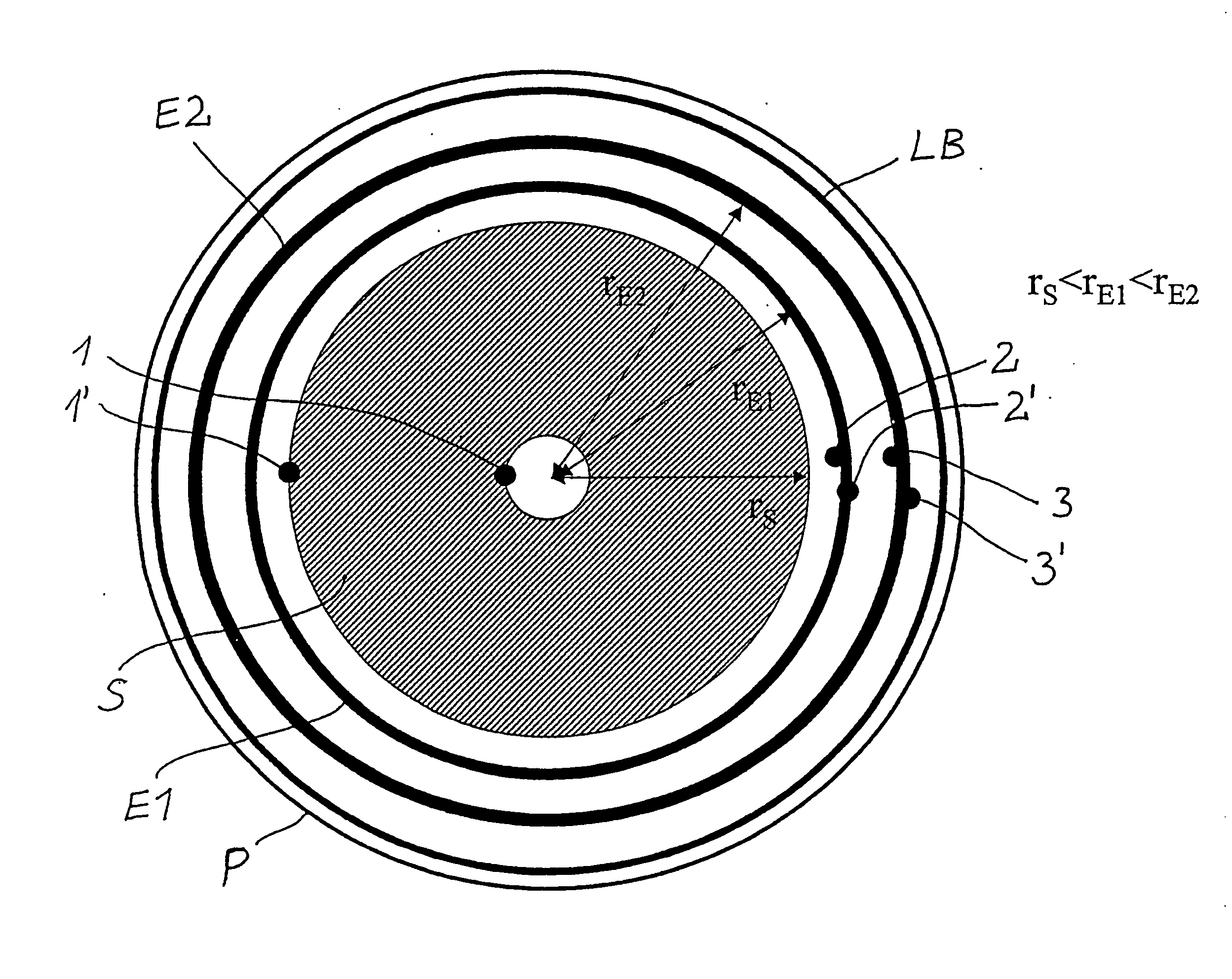
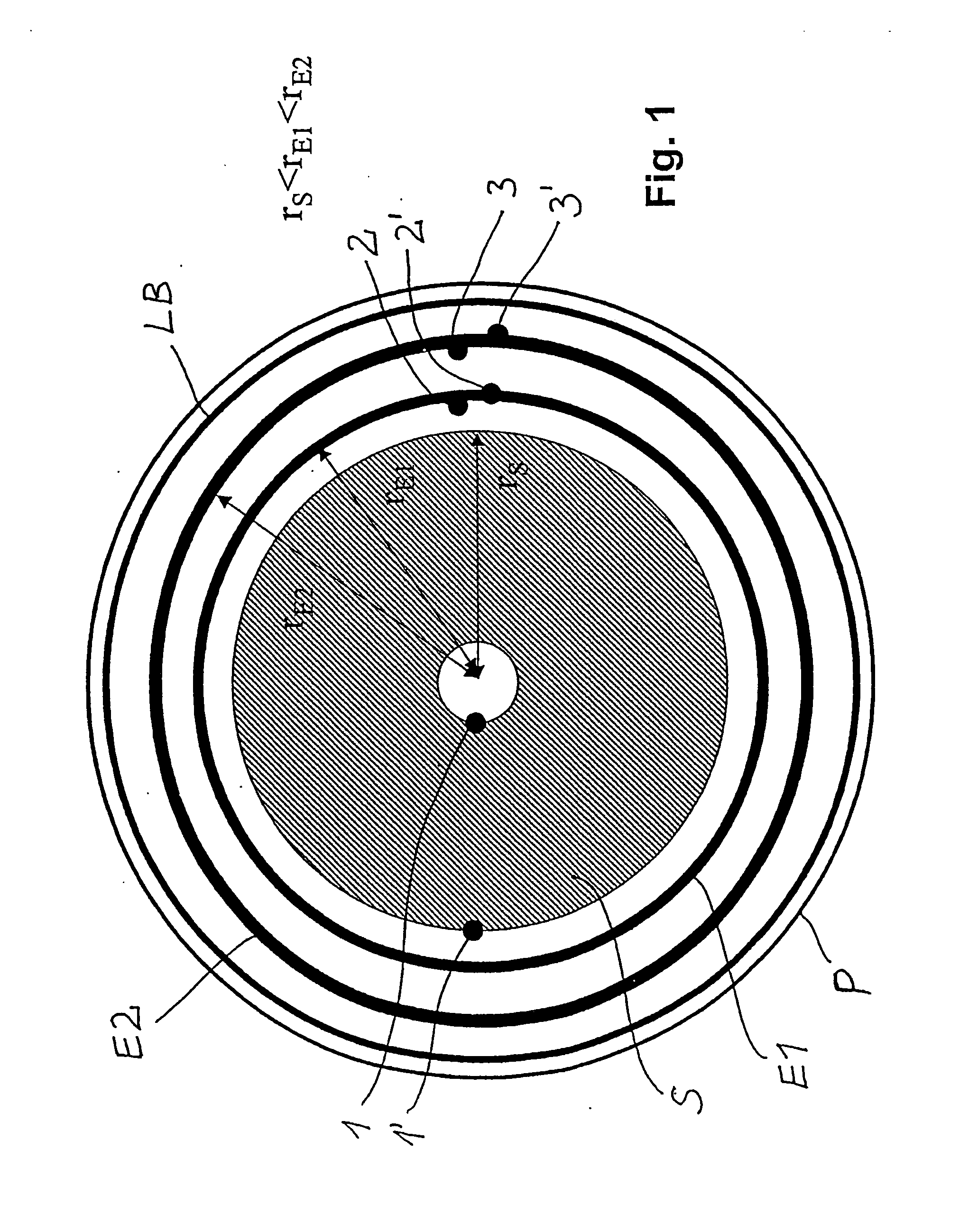
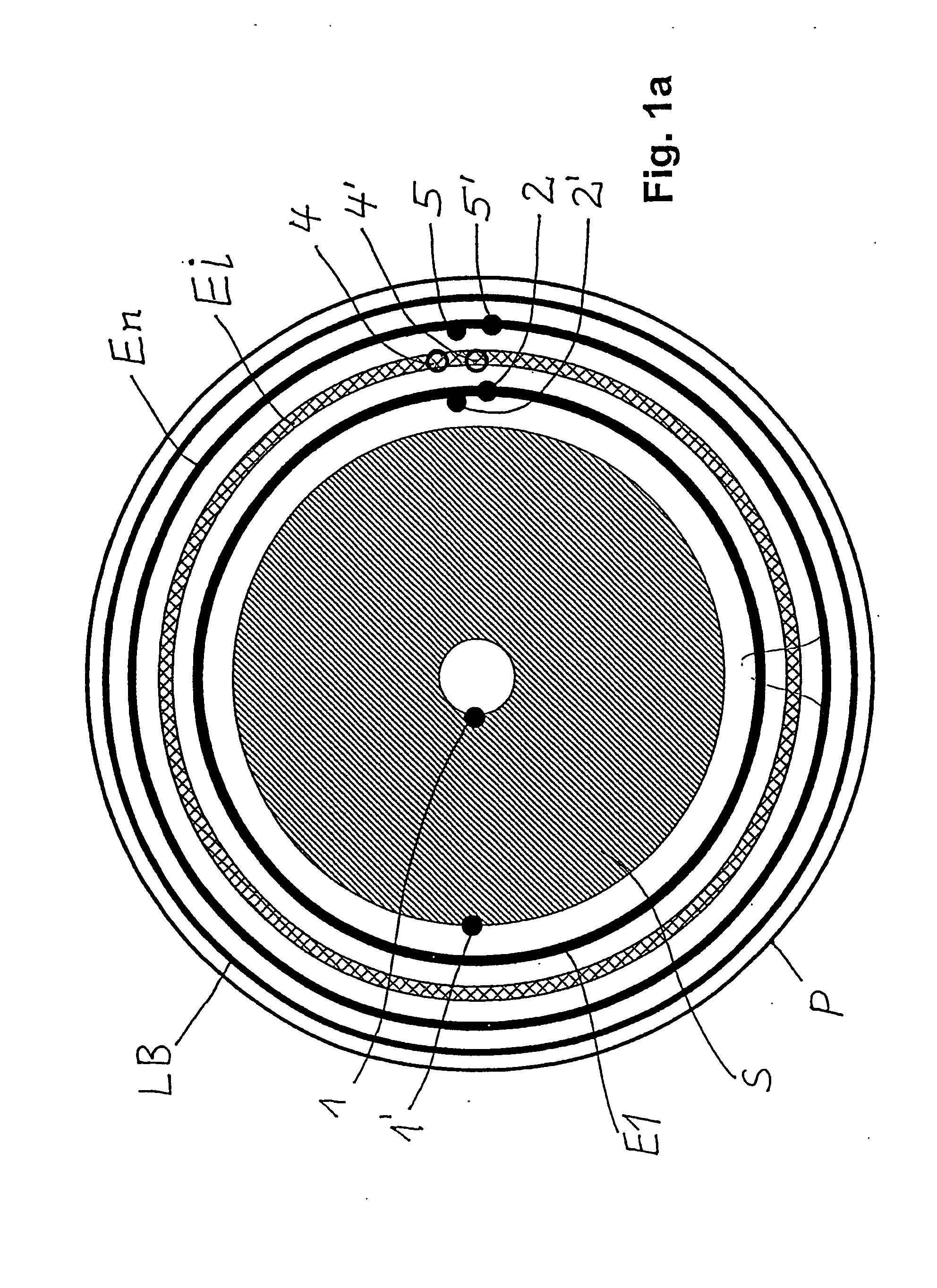
[0039]FIGS. 1 and 1a show the fundamental structure of an arrangement according to the invention of a transmitting coil S and of a plurality of receiving coils E1 and E2 on a circular printed circuit board P. The transmitting coil S is preferably a flat coil having a radius rS and a circular coil surface area FS and having windings that are wound essentially spirally (not shown here) and also having the coil ends 1, 1′. The annular receiving coil E1 has windings that are wound essentially spirally or circularly, preferably in the form of a printed flat coil having the coil ends 2, 2′; likewise, the annular receiving coil E2 has windings that are wound essentially spirally to circularly, preferably in the form of a printed flat coil having the coil ends 3, 3′. In the example shown, the receiving coils E1 and E2 are arranged in a plane approximately concentrically around the transmitting coil S. The radius rE1 of the receiving coil E1 is greater than the maximum radius rS of the trans...


PUM


Abstract

The invention relates to a preferably ferriteless inductive proximity switch having at least one transmitting coil, one oscillator circuit and at least two receiving coils arranged in the alternating magnetic field of the transmitting coil, whereby the transmitting coil and the receiving coil are arranged adjacent to each other on a printed circuit board, and also having an evaluation circuit connected to the receiving coil for evaluating the received signal of the receiving coils when a target approaches the proximity switch. The receiving coils (E1, E2, Ei, En, 7, 8, 12, 13) as well as the transmitting coil (S, SA, 11) are made up of at least one polygonal or annular or elliptical winding and they each delineate a polygonal or annular or elliptical coil surface area, whereby either the transmitting coil (S, 11) is surrounded by a first receiving coil (E1, 12) which is, in turn, surrounded by a second receiving coil (E2, 13) and optionally, said second receiving coil is surrounded by a third or nth peripheral receiving coil (En), or a first receiving coil (7) is surrounded by the second receiving coil and optionally, said second receiving coil is surrounded by a third or nth receiving coil, whereby the nth receiving coil is peripherally surrounded by the transmitting coil (SA), so that in both alternatives, the coil surface area spanned by the outermost coil in each case completely covers all of the coil surface areas of the other coils situated further towards the inside and moreover, in a perpendicular parallel projection onto the coils, the transmitting coil (S, 11, SA) is at a distance from its closest adjacent receiving coil (E1, E2, 12, 13, En) without the transmitting coils and / or the receiving coils overlapping.

Description

FIELD OF THE INVENTION[0001]The invention relates to an inductive proximity switch based on the transformer coupling-factor principle, having at least one transmitting coil, one oscillator circuit and at least two receiving coils arranged in the alternating magnetic field of the transmitting coil, whereby the transmitting coil and the receiving coil are arranged adjacent to each other on a printed circuit board, and also having an evaluation circuit connected to the receiving coils, whereby, when a target approaches the proximity switch, said evaluation circuit generates a switching signal on the basis of the evaluation of the received signals of the receiving coils, according to the generic part of Claim 1.DESCRIPTION OF RELATED ART[0002]Inductive proximity switches are sensors that react contact-free, i.e. without direct contact, to the approach of a metal or non-metal object, a target. Two basic principles are known when it comes to structuring inductive proximity switches.[0003]...

Claims


Application Information

Patent Timeline
Patent Type & Authority Applications(United States)
IPC IPC(8): H03K17/95
CPCH03K17/9525H03K17/9505H03K2017/9527
Inventor KUHN, THOMAS
Owner PEPPERL FUCHS GMBH
Why Eureka
Try Eureka