
Switching systems

Active Publication Date: 2008-08-28
ANALOG DEVICES INC
View PDF2 Cites 2 Cited by
  • Summary
  • Abstract
  • Description
  • Claims
  • Application Information

AI Technical Summary

Benefits of technology

[0004]It is a further object of this invention to provide such an improved cross point switching system which has reduced area, reduced conductor numbers and length, and reduced numbers of devices per point cell.
[0012]The invention results from the realization that an improved smaller, faster, higher bandwidth and higher yield cross point switching system can be achieved by distributively associating with each output row of point cells or each subset of point cells in each output row one or more of a: memory device for storing an address identifying a cell in its associated output row and a decoder device responsive to the memory device for actuating the associated enable circuit to operate the transconductance device of the identified cell; a bias device, an output cascode device; and from the further realization that cross point switching systems and switching systems in general can be benefited by a bias device including a current mirror having an input reference portion responsive to a reference current and a co-located output local portion for reproducing that current as the bias current.

Problems solved by technology

When a number of outputs are connected to one input, that input experiences an increasing load which slows down the response.
One problem with large arrays of switching cells is that the more inputs m and outputs n there are, the larger must be the associated conductors.
The larger the Rc and Cc, the greater the time constant, τ, and this leads to slower response time and lower signal path bandwidth.

Method used


Image

  • Switching systems
  • Switching systems
  • Switching systems

Examples


Embodiment Construction

[0032]Aside from the preferred embodiment or embodiments disclosed below, this invention is capable of other embodiments and of being practiced or being carried out in various ways. Thus, it is to be understood that the invention is not limited in its application to the details of construction and the arrangements of components set forth in the following description or illustrated in the drawings. If only one embodiment is described herein, the claims hereof are not to be limited to that embodiment. Moreover, the claims hereof are not to be read restrictively unless there is clear and convincing evidence manifesting a certain exclusion, restriction, or disclaimer.

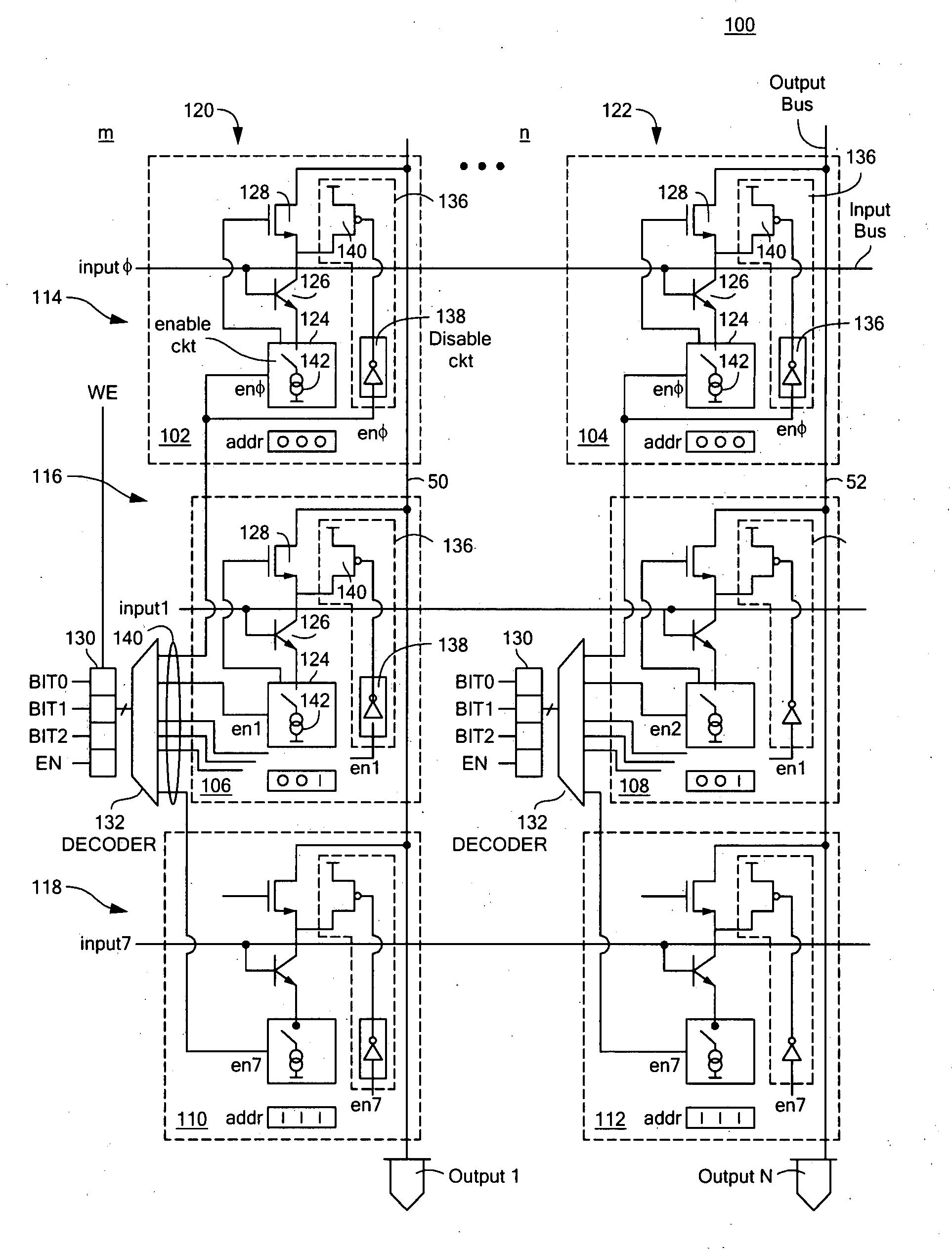
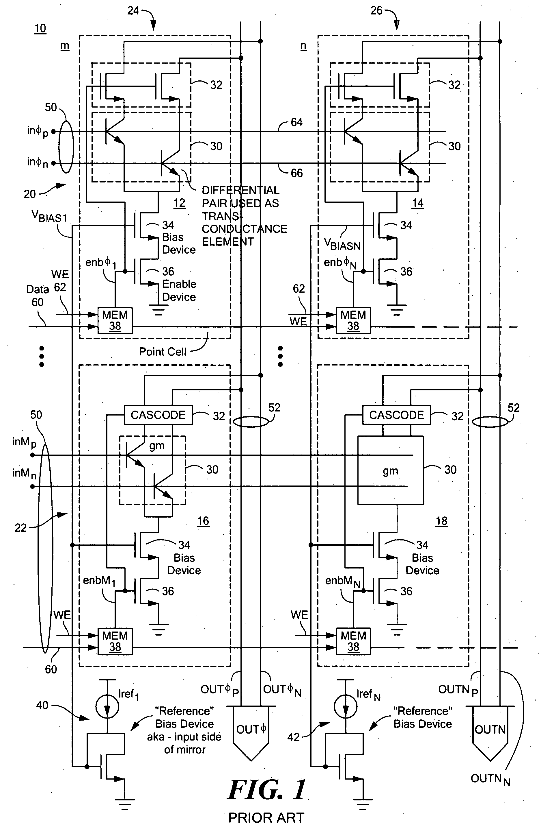
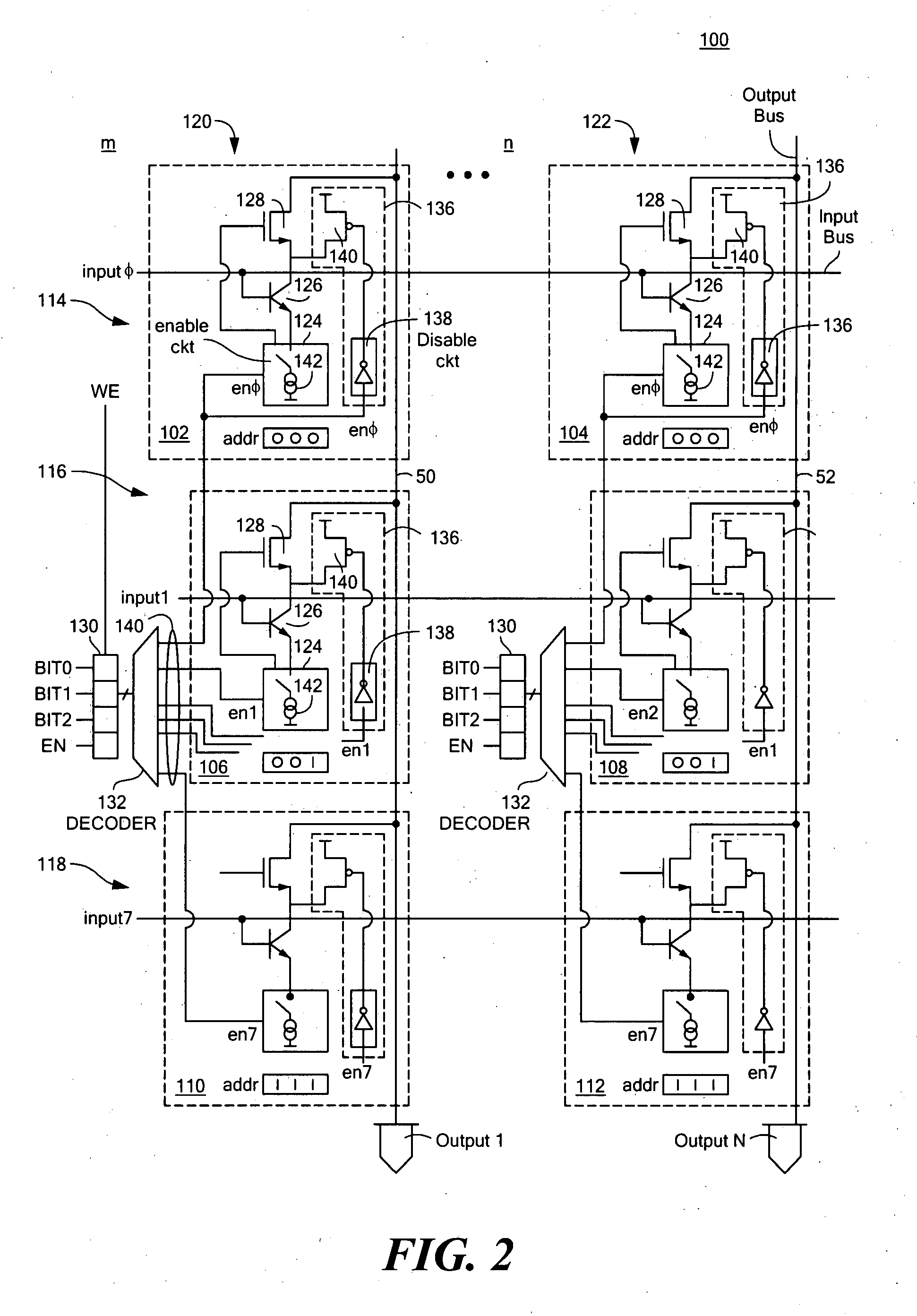
[0033]There is shown in FIG. 1 a prior art cross point switching system 10 including an array of cells 12, 14, 16 and 18 arranged in m input rows and n output rows which intersect uniquely to find the position of each cell. For example, input row 20 includes cells 12 and 14 while input row 22 includes cells 16 and 18. Outpu...


PUM


Abstract

Distributively associated with each output row of point cells or each subset of point cells in each output row is one or more of a: memory device for storing an address identifying a cell in its associated output row and a decoder device responsive to the memory device for actuating the associated enable circuit to operate the transconductance device of the identified cell; a bias device, and an output cascode device; and also disclosed as switching systems having a bias device including a current mirror with an input reference portion responsive to a reference current and a co-located output local portion for reproducing that current as the bias current.

Description

FIELD OF THE INVENTION[0001]This invention relates to improvements in cross point switching systems and also to a distributed bias device with co-located current mirror portions for use in switching systems generally as well as to cross point switching systems.BACKGROUND OF THE INVENTION[0002]Conventional switching systems, e.g. cross point switching systems are under constant pressure to increase the number of switched inputs and outputs and their switching speed. Non-blocking cross-point switching systems, those in which any number of outputs can be connected to an input and as many as all outputs can be activated at one time are under particular pressure to improve because of the growing video / communications market. Typically the array of switching point cells is arranged in m input rows and n output rows which intersect to uniquely identify each switching cell. When a number of outputs are connected to one input, that input experiences an increasing load which slows down the res...

Claims


Application Information

Patent Timeline
IPC IPC(8): H04Q3/52
CPCH04Q3/521H04Q2213/1302H04Q2213/1332H04Q2213/13305H04Q2213/1304
Inventor BANKMAN, JESSE R.TAM, KIMO Y. F.
Owner ANALOG DEVICES INC
Learn More