
Image processing apparatus

Inactive Publication Date: 2008-08-28
KOWA CO LTD
View PDF4 Cites 39 Cited by
  • Summary
  • Abstract
  • Description
  • Claims
  • Application Information

AI Technical Summary

Benefits of technology

[0018]In accordance with the configuration described above, distortions in an optical system used for actual photography are corrected, an accurate three-dimensional measurement process involving an ocular fundus image is performed, and / or an accurate ocular fundus image that corresponds to the three-dimensional measurement results can be provided in an image processing apparatus for stereographically photographing an ocular fundus of a subject's eye via an stereo photographic optical system and performing a three-dimensional shape measurement process based on the resulting photograph image data. Therefore, excellent effect is obtained in that the stereo shape of the ocular fundus of a subject's eye can be accurately evaluated and misdiagnoses and other problems can be avoided.
[0019]Also, calibration measurement and computation can be easily carried out without changing other photographic and computational conditions by using a model eye for modeling the shape and optical characteristics of a subject's eye.
[0020]An examiner can readily ascertain the state of the ocular fundus of the subject's eye via stereographic observation by producing left and right image data corrected based on the shape distortion correction and stereographically displaying the data using a stereo monitor.

Problems solved by technology

Image distortions are present in the optical system of a photography apparatus such as a fundus camera.
These distortions include those that are presumed to exist in advance in terms of the design of the optical system, as well as those that are produced by errors in manufacturing that vary depending on individual optical systems.
However, it is difficult to say that such a conventional correction process accurately reflects the characteristics of the optical system used in actual photography, and it is highly possible that some type of error will occur in the three-dimensional measurement results of the ocular fundus.

Method used


Image

  • Image processing apparatus
  • Image processing apparatus
  • Image processing apparatus

Examples


Embodiment Construction

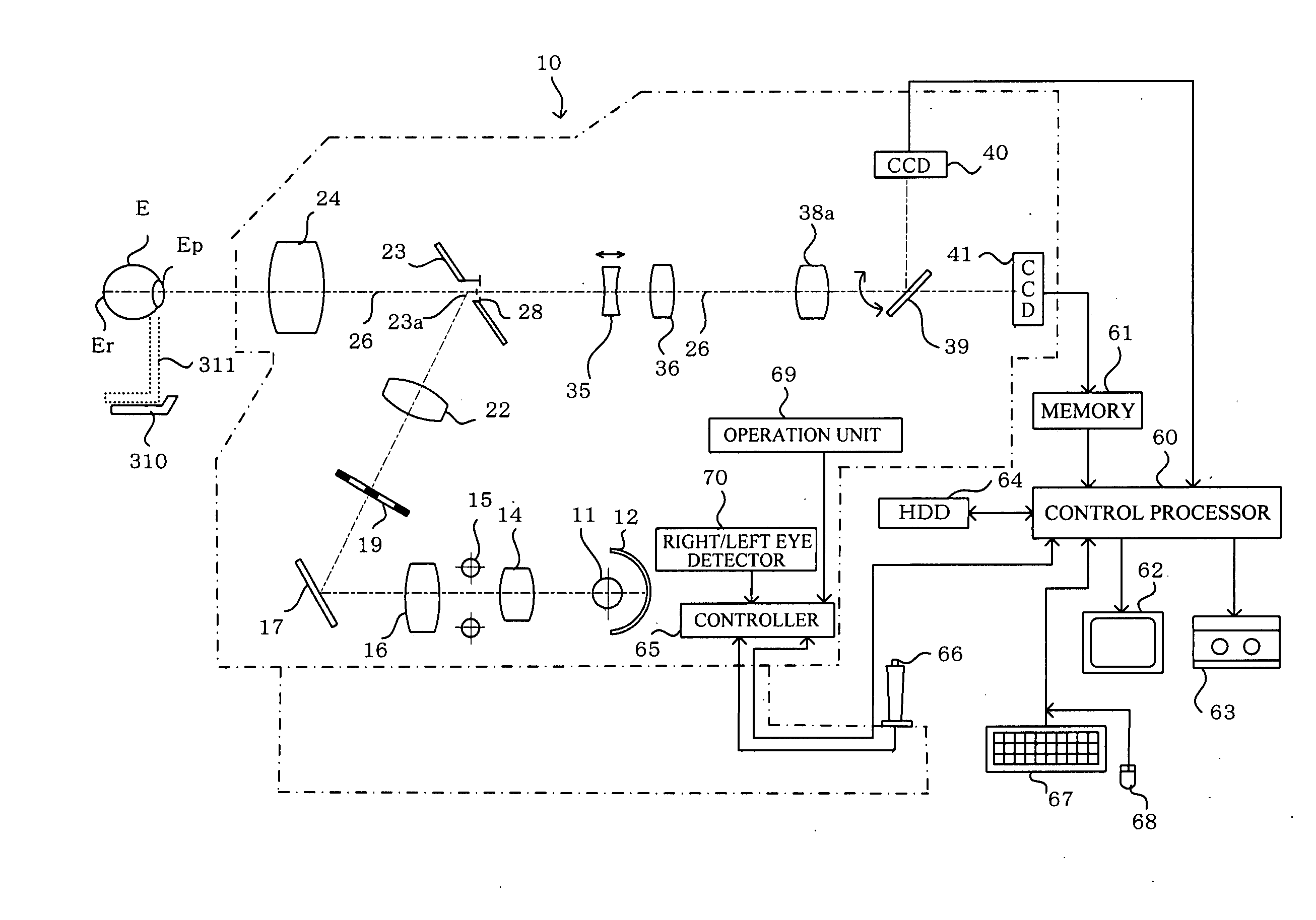
[0036]Described below is the present invention embodied as an ophthalmic measuring apparatus for producing a stereo photograph of the ocular fundus of a subject's eye via a stereo photographic optical system and processing the resulting photographic image data for three-dimensional measurement and display.

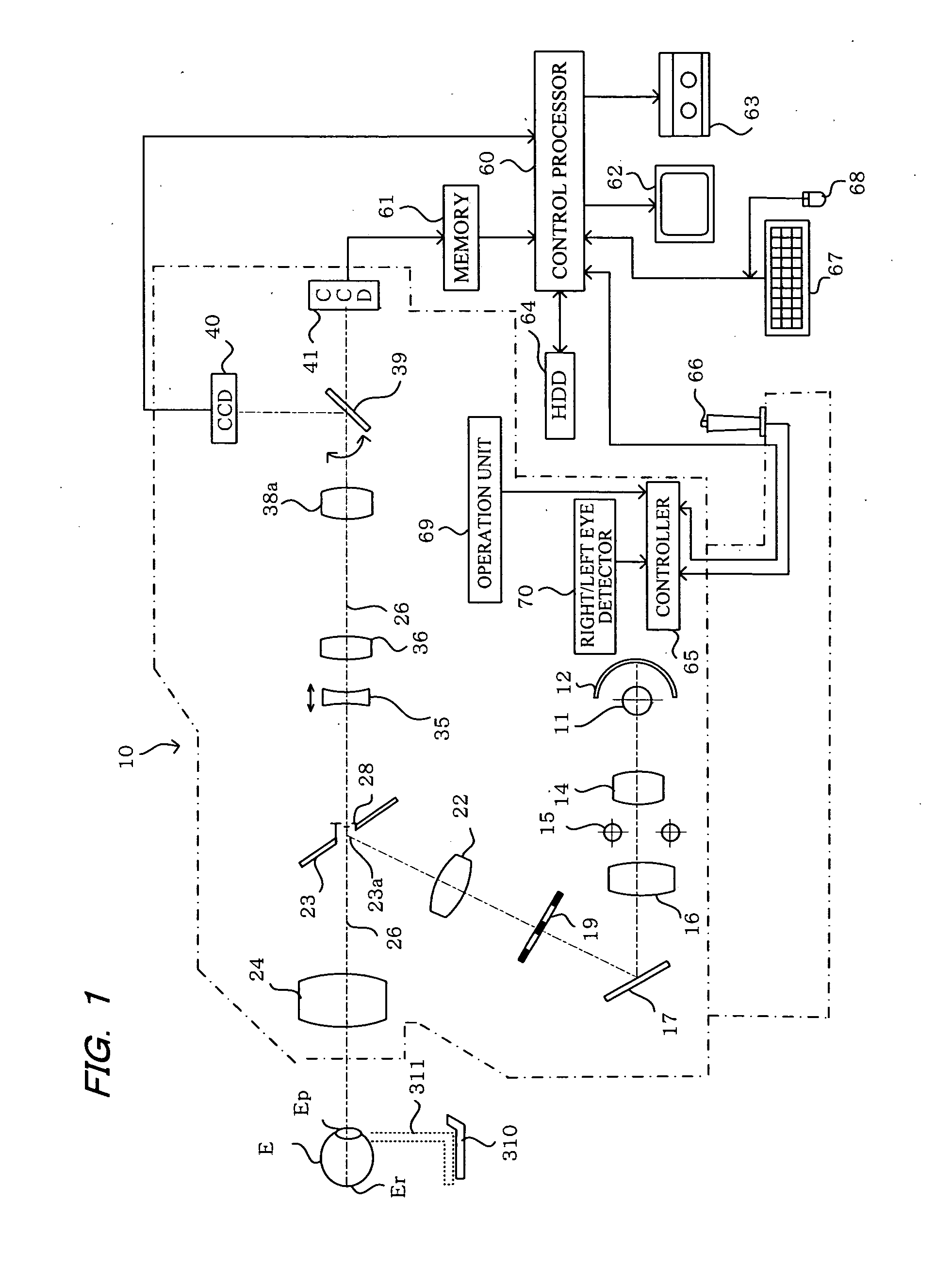
[0037]In FIG. 1, a fundus camera 10 enclosed and depicted by the alternate long and short dash line is provided with an observation lamp 11 that emits infrared and visible illumination light and is disposed in the center of the curvature of a spherical mirror 12. The light from the observation lamp 11 and the spherical mirror 12 travels though a condenser lens 14, a strobe light 15 as a photographic light source, and a condenser lens 16, and is then incident on the total reflection mirror 17.

[0038]The illumination light reflected by the total reflection mirror 17 is transmitted through a relay lens 22 via an illumination stop 19, is reflected by an apertured total reflection mirror...


PUM


Abstract

A model eye that models the optical characteristics of a human eye and is endowed with a grayscale pattern on the ocular fundus model surface is stereographically photographed with a parallax via a stereo photographic optical system. Photographed images are processed to provide calibration data for correcting the shape distortions of the stereo photographic optical system. The calibration data is used to correct a distortion-affected shape data and parallax images obtained in stereographic photography of the actual ocular fundus of a subject's eye. The shape distortion-corrected parallax image is used for a three-dimensional measurement process and 3D display on a stereo monitor. This allows an accurate three-dimensional measurement to be carried out and an accurate fundus image to be produced. The examiner can accurately evaluate the stereo shape of the ocular fundus of the subject's eye.

Description

BACKGROUND OF THE INVENTION[0001]1. Field of the Invention[0002]The present invention relates to an image processing apparatus, and more particularly relates to an image processing apparatus for stereographically photographing the ocular fundus of a subject's eye with a prescribed parallax via an ocular fundus photographic optical system and for processing the resulting parallax images for three-dimensional shape measurement and three-dimensional display.[0003]2. Description of the Prior Art[0004]Conventionally known are a fundus camera and other image processing apparatuses for photographing a stereo image of the ocular fundus of a subject's eye in order to understand the shape of the ocular fundus of the subject's eye for the purpose of diagnosing glaucoma or performing other examinations. For example, an apparatus is known in which a photographic stop inside an optical system in a fundus camera is moved to different positions that are offset to the left and right (or up and down)...

Claims


Application Information

Patent Timeline
IPC IPC(8): A61B3/14G06K9/60
CPCG06T7/002G06T7/0075A61B3/14G06T2207/30041G06T2207/10012G06T7/593G06T7/85
Inventor FUJITA, HIROSHINAKAGAWA, TOSHIAKISUZUKI, TAKAYOSHI
Owner KOWA CO LTD
Learn More