
System For Distributed Measurement of the Curves of a Structure

a technology of distributed measurement and curves, applied in the direction of instruments, structural/machine measurement, converting sensor output, etc., can solve the problems of high repair cost, inability to know precisely the exact, and methods that are not effective in terms of precision, and cannot be fast enough

Inactive Publication Date: 2008-08-28
COMMISSARIAT A LENERGIE ATOMIQUE ET AUX ENERGIES ALTERNATIVES
View PDF14 Cites 101 Cited by
  • Summary
  • Abstract
  • Description
  • Claims
  • Application Information

AI Technical Summary

Benefits of technology

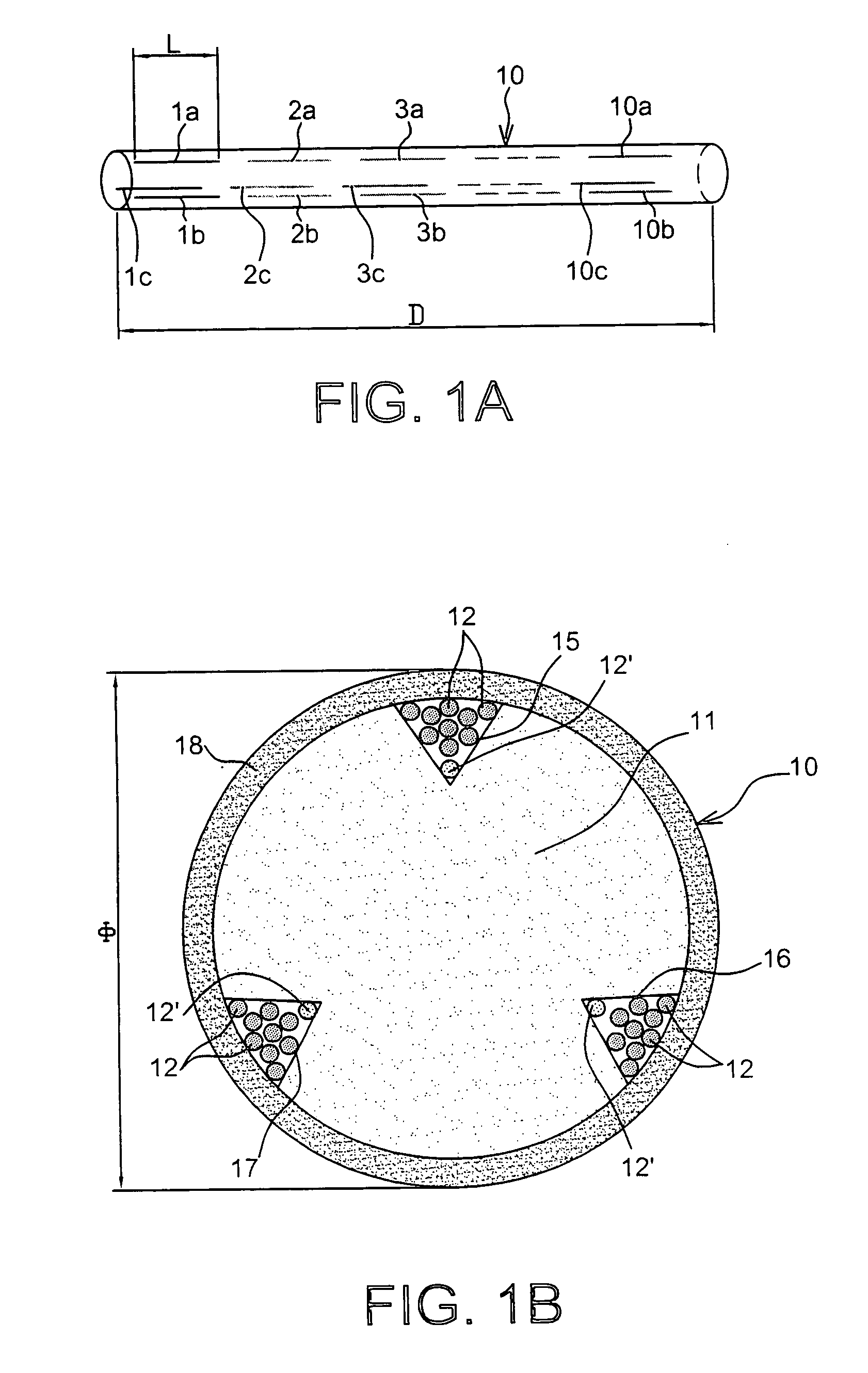
[0014]Advantageously, said system includes at least one additional optical fibre that makes it possible to perform a temperature self-compensation, which can comprise Bragg gratings distributed along its entire length. This additional optical fibre can be inserted freely into a low-friction plastic capillary. Advantageously, the device includes an outer casing. The reinforcement is advantageously obtained by pultrusion of a glass-epoxy- or glass-vinyl ester-type composite material. Advantageously, metal fasteners can be crimped on the reinforcement. The fibres can be recollected via a multistrand optical cable that transmits the measurement to the processing means.
[0026]The identification of a rupture in the structure concerned (due to a ground collapse) is made possible by an interrogation by the two ends of the device. The identification of the sensors present on the line makes it possible to locate the rupture. This advantage is possible with Bragg grating technology or B-OTDR technology.

Problems solved by technology

In the field of civil engineering construction (buildings, bridges, roadways, railway tracks, etc.), non-uniform settlements and even unforeseen collapses (localised collapses) can cause serious accidents, aboveground and underground, and lead to very high repair costs.
Such events can be due to the existence of natural or artificial cavities (mines, tunnels, etc.) that are not indexed or, if they are known, insufficiently consolidated and overloaded.
Such means (indirect) do not make it possible to know precisely the exact behaviour of a ground settlement.
However, these methods are neither effective enough in terms of precision, nor fast enough, and are moreover expensive to carry out because they require the use of personnel.
When bending occurs in the diametral plane passing through such a corrugated area, some of the light injected into the fibre is lost toward the outside, in proportion to the magnitude of this bend.
This leads to a practical difficulty in outside use where the climatic conditions are not controlled.
Moreover, such sensors require as many fibres as points of measurement (one point of measurement per fibre to prevent any ambiguity) and therefore become very difficult and expensive to wire when there is a large number of points of measurement.
Moreover, the measurement principle does not mention methods for compensation of fluctuations in optical intensity, other than those expected, which are capable of distorting the measurement.
Such fluctuations can occur as a result of connection problems, ageing of glued joints, microbends along the measurement fibre, and so on.
In addition, as it is necessary to calibrate the sensors one-by-one and the setting can change over time (for the same reasons as above), thereby necessitating periodic recalibration of the sensors, which is costly and not always feasible at the site, in particular if the structure is sealed underground.

Method used


Image

  • System For Distributed Measurement of the Curves of a Structure
  • System For Distributed Measurement of the Curves of a Structure
  • System For Distributed Measurement of the Curves of a Structure

Examples


embodiment

Metrological Properties of Bragg Gratings

[0037]The wavelength of a Bragg grating varies directly with the temperature T and the deformations ε according to the axis of the fibre.

[0038]The relative variation of the Bragg wavelength of a Bragg grating (free grating, unglued) as a function of temperature, is thus written:

ΔλBλB=aΔT=(α+ξ)ΔT≈7·10-6·ΔT(1)

[0039]At the wavelength of 1.55 μm, this coefficient is on the order of 10 to 12 pm / K according to the optical fibres. When the Bragg grating is glued to a composite structure (glass-epoxy), it undergoes a deformation corresponding to the thermal dilation of this structure and the temperature law is rewritten as follows:

ΔλBλB=a′·ΔT=((1-pe)·αs+ξ)ΔT≈13·10-6·ΔT(2)

[0040]Similarly, the relative variation in Bragg wavelength as a function of the deformation involves the deformation itself and the variation in refraction index induced by this deformation (elasto-optical effect) according to the relation:

ΔλBλB=(1-pe)ɛ=1-(ne22(p12(1-v)-p11v))·ɛ=0,7...


PUM


Abstract

The invention relates to a system for distributed or dispersed measurement of axial and bending deformations of a structure including at least one threadlike device (10) equipped for the distributed or dispersed measurement of these axial and bending deformations, and means for processing measurement signals generated by said device, in which each device includes a cylindrical reinforcement (11) supporting, at its periphery, at least three optical fibres (12) locally parallel to the axis of the reinforcement, and in which the processing means implement means for spectral or time division multiplexing of signals coming from optical fibres.

Description

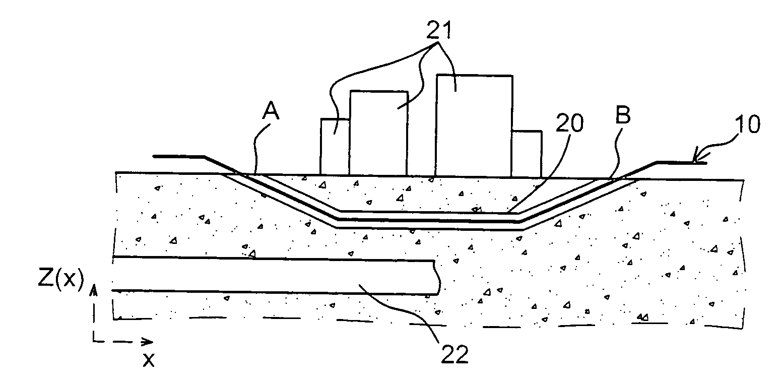
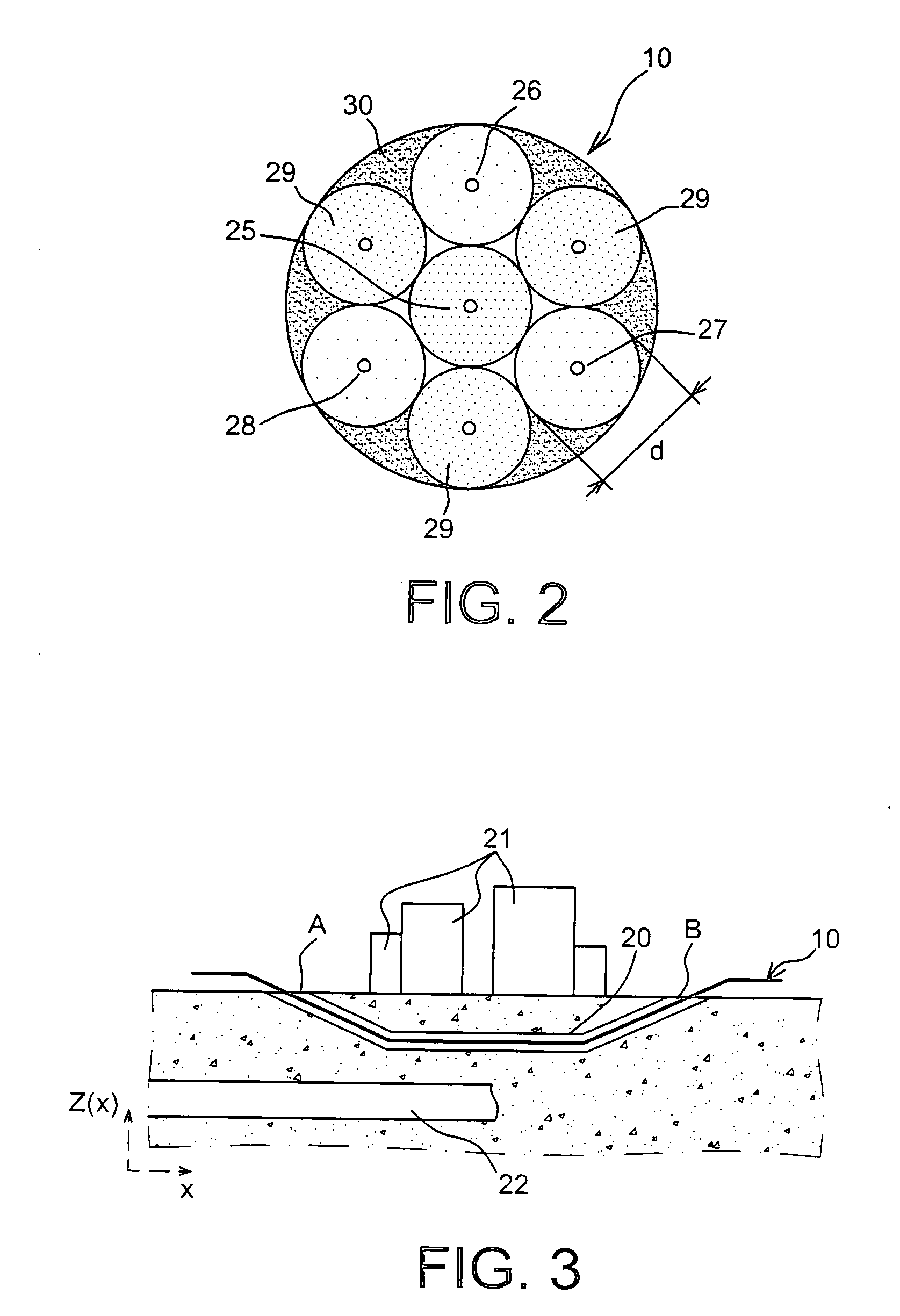
TECHNICAL FIELD[0001]The invention relates to a system for distributed measurement of the curves of a structure, including a threadlike cable device equipped for such a measurement and means for processing measurement signals generated by said device.PRIOR ART[0002]In the field of civil engineering construction (buildings, bridges, roadways, railway tracks, etc.), non-uniform settlements and even unforeseen collapses (localised collapses) can cause serious accidents, aboveground and underground, and lead to very high repair costs. Such events can be due to the existence of natural or artificial cavities (mines, tunnels, etc.) that are not indexed or, if they are known, insufficiently consolidated and overloaded.[0003]Public works companies want to have a measurement system suitable for existing structures (or structures under construction), making it possible to monitor the precise changes (spatially, along a horizontal plane) in the ground settlement and to set off an alarm in the ...

Claims


Application Information

Patent Timeline
IPC IPC(8): G01B11/16G01L1/24G01D5/353G01M5/00G01M11/08G02B6/02G02B6/44
CPCG01M5/0025G01M5/0041G01M5/0091G01D5/35354G02B6/022G01D5/35316G01D5/35364G01M11/085
Inventor MAGNE, SYLVAINFERDINAND, PIERRE
Owner COMMISSARIAT A LENERGIE ATOMIQUE ET AUX ENERGIES ALTERNATIVES
Learn More