Speaker

a technology of speaker and spider, applied in the field of speakers, can solve the problems of insufficient reduction of spider stiffness, inability to increase the sound pressure level in the bass range, inability to adequately reduce spider stiffness, etc., and achieve the effect of extending the frequency band for sound reproduction and reducing thickness and weigh

Inactive Publication Date: 2008-08-28
MINEBEA CO LTD
View PDF0 Cites 27 Cited by
  • Summary
  • Abstract
  • Description
  • Claims
  • Application Information

AI Technical Summary

Benefits of technology

[0013]The present invention has been made in light of the above problems, and it is an object of the present invention to provide a speaker in which, while achieving a lower profile, a vibration system is free from the rolling phenomenon and noise generation even when a large input is applied, and a wide reproduction frequency range can be achieved by setting the resonance frequency to be low.
[0028]The speaker structured as describe above, while achieving reduction in thickness and weight, is free from generation of noises due to, for example, the rolling phenomenon of the vibration system even when a large output is applied, and can set resonance frequency to be low thereby extending a frequency band for sound reproduction.

Problems solved by technology

H9-238396, since it is not possible to set the outer diameter of the spider to be larger than the inner diameter of the voice coil bobbin, the stiffness of the spider cannot be adequately reduced thus failing to lower its lowest resonance frequency (hereinafter referred to simply as “resonance frequency” as appropriate), that is to say that the sound pressure level cannot be increased in the bass range.
H9-238396, the stiffness of the spider cannot be adequately reduced thus failing to lower its resonance frequency, that is to say, the sound pressure level cannot be increased in the bass range.

Method used


Image

  • Speaker
  • Speaker
  • Speaker

Examples


first embodiment

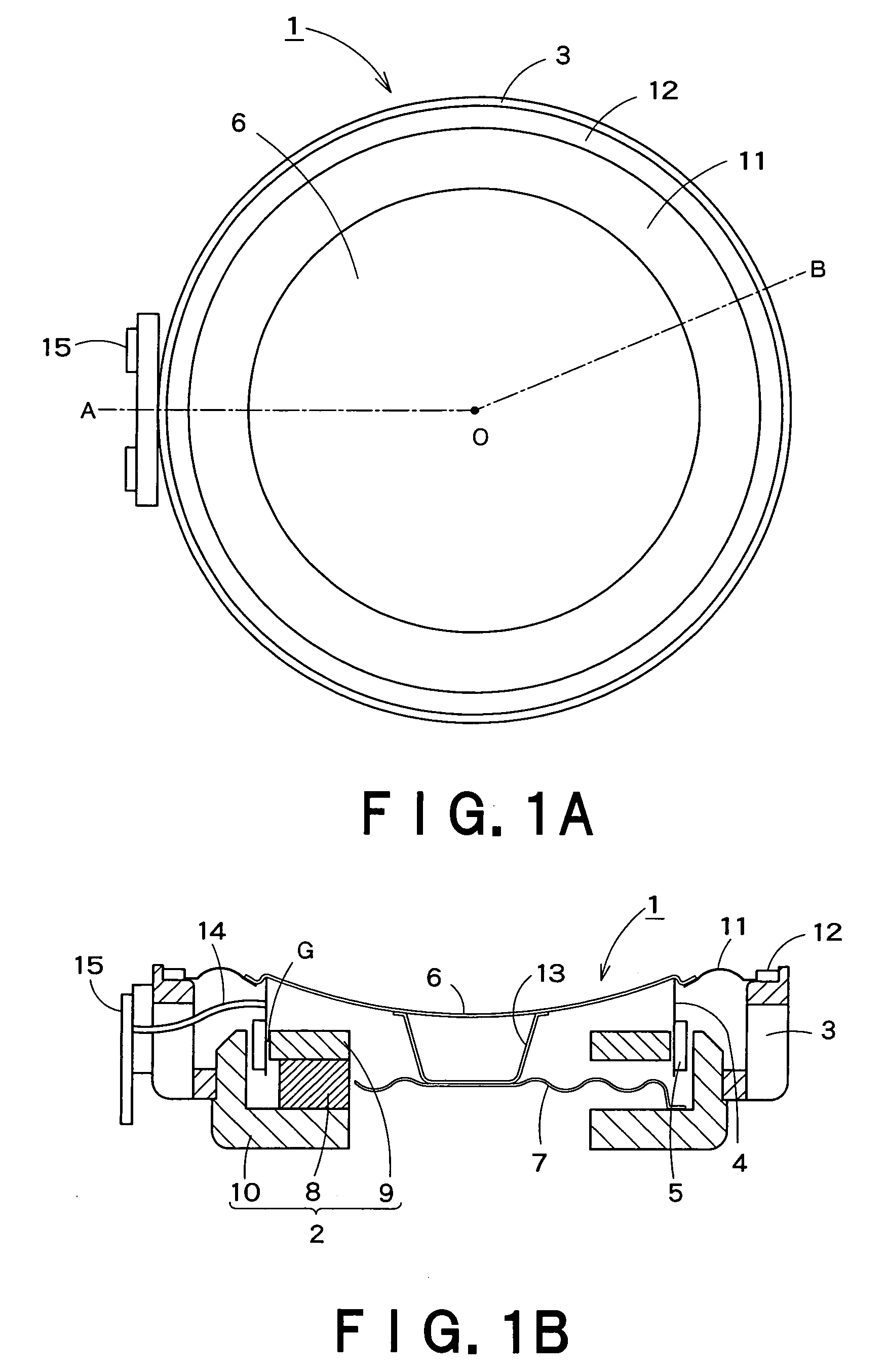
[0061]Accordingly, in the speaker 1 reduction can be achieved in speaker size and profile, the rolling phenomenon of the vibration system or noises are prevented when a large input is applied, and the resonance frequency can be lowered thus enabling an increase in the sound reproduction frequency band.

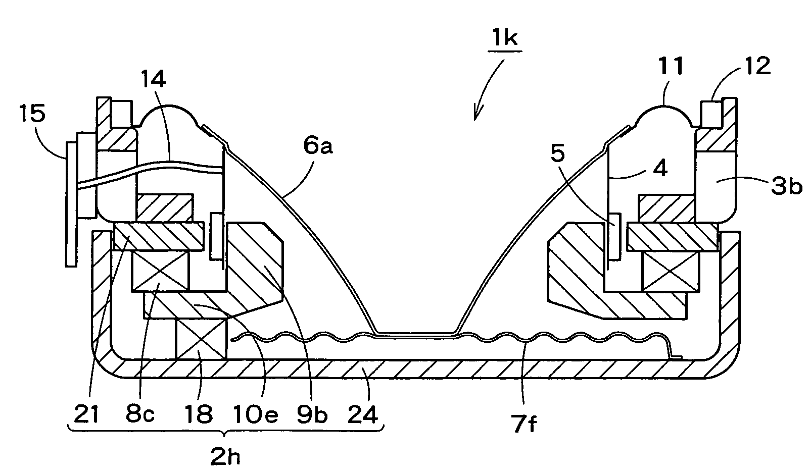
[0062]A second embodiment of the present invention will be described with reference to FIG. 2. Referring to FIG. 2, a speaker la according to the second embodiment is structured essentially the same as the speaker 1 according to the first embodiment with distinct differences residing in diaphragm shape and connection structure between a diaphragm and a spider. In explaining the example of FIG. 2, any component parts corresponding to those in FIG. 1B are denoted by the same reference numerals, and a detailed description thereof will be omitted below with focus put on the differences.

[0063]The speaker 1a of FIG. 2 includes a diaphragm 6a which is formed in a truncated circular cone shap...

second embodiment

[0085]The speaker 1h of FIG. 9A includes a magnet unit composed of a ring magnet 8a having a plurality (eight in FIG. 9B) of grooves S on the front face as shown in FIG. 9B. In the speaker 1h, a spider 7c has its leg distal end tips attached in respective grooves S. Otherwise, the speaker 1h is structured substantially the same as the speaker 1a according to the

[0086]In the speaker oh structured as described above, since the magnet unit (the ring magnet 8a) is of a one-piece structure, the assembly work can be simplified.

eighth embodiment

[0087]the present invention will be described with reference to FIG. 10A and 10B. Referring to FIGS. 10A and 10B, a speaker 1i according to the eighth embodiment differs from the speaker 1h according to the seventh embodiment in magnet unit composition and attachment structure of a spider.


PUM


Abstract

A speaker includes: a magnetic circuit; a voice coil bobbin; a voice coil; a diaphragm; a frame to which the outer circumference of the diaphragm is connected via a suspension; and a spider to support the center area of the diaphragm. A magnet unit, a pole piece, a pole piece, and a yoke are included in the magnetic circuit. The yoke has a ring shape with a center opening, and is disposed at the rear of the magnet unit. The magnet unit has a ring structure having a plurality of empty portions arranged equiangularly, and the spider includes a main body and a plurality of legs extending radially outwardly from the main body and is disposed inside the magnetic circuit such that distal end tips of the legs pass beyond the inner diameter of the ring structure of the magnet unit.

Description

BACKGROUND OF THE INVENTION[0001]1. Field of the Invention[0002]The present invention relates to a speaker for use in miscellaneous audio equipment.[0003]2. Related Art[0004]A speaker is extensively used not only in home or car audio equipment but also in miscellaneous electronic equipment such as a personal computer, a mobile phone, a game instrument, a thin screen TV, and the like. A speaker used in such a piece of equipment, even if small and thin in size, is demanded to provide an excellent sound quality and to have a large input capacity.[0005]FIG. 14 shows a conventional speaker. Referring to FIG. 14, a speaker 100 generally includes: a magnetic circuit 104 composed such that a magnet 101 is sandwiched between a pole piece 102 and a yoke 103 formed in a pot shape wherein a magnetic gap 105 is formed; a frame 106 having its inner circumference connected to the outer circumference of the yoke 103; a surround 107 having its outer edge connected to the front circumferential face o...

Claims


Application Information

Patent Timeline
Patent Type & Authority Applications(United States)
IPC IPC(8): H04R9/06
CPCH04R7/24H04R9/025H04R2499/15H04R2499/11H04R9/043
Inventor SATO, EIJI
Owner MINEBEA CO LTD
Why Eureka
Try Eureka