
Microsurgical Illuminator with Adjustable Illumination

Inactive Publication Date: 2008-08-28
SYNERGETICS
View PDF6 Cites 18 Cited by
  • Summary
  • Abstract
  • Description
  • Claims
  • Application Information

AI Technical Summary

Benefits of technology

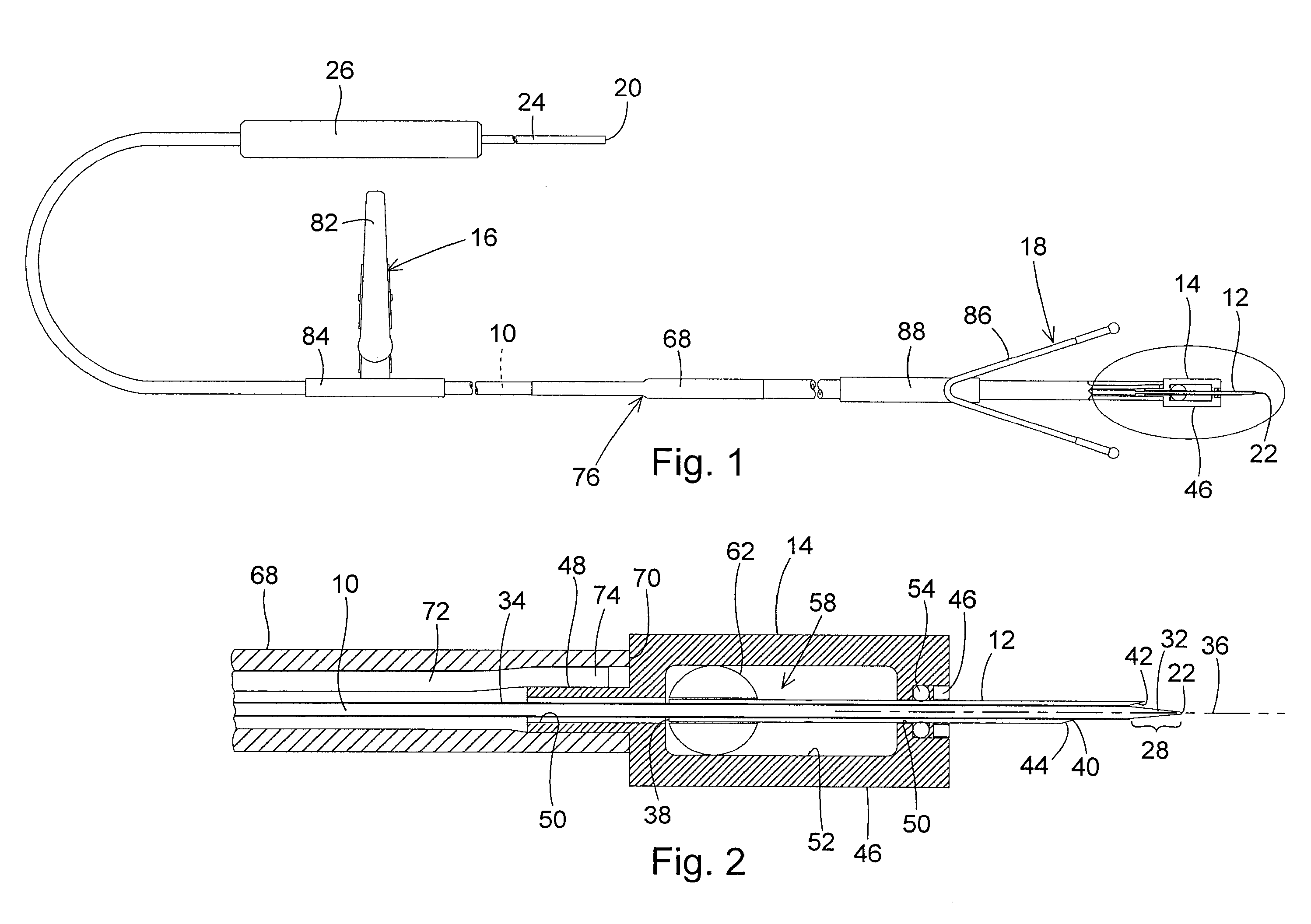
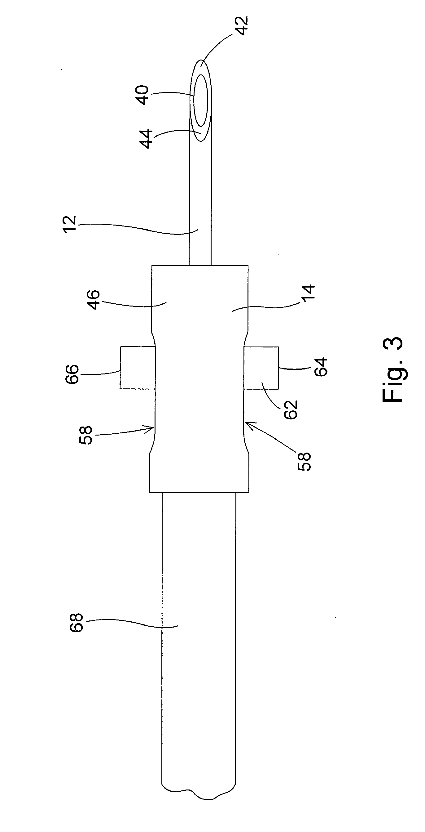
[0013]A slide bar is secured to the needle adjacent the needle first end. Opposite ends of the slide bar extend from the needle first end through the pair of window openings in the housing. These opposite ends of the slide bar are positioned outside of the housing where they are accessible by the surgeon for gripping and manipulating the slide bar through the housing interior bore. Moving the slide bar forward through the housing toward the optic fiber distal end causes the needle to move over the optic fiber distal end, containing the conical exterior surface of the optic fiber in the interior of the needle. Moving the slide bar rearward or toward the optic fiber proximal end causes the needle to be retracted over the optic fiber distal end surface, exposing the fiber distal end surface from the beveled surface of the needle.
[0014]During use of the adjustable chandelier illuminator, the slide bar is moved forward positioning the long, sharp beveled end surface of the needle over the optic fiber conical surface. The long beveled surface of the needle is required for ease of insertion of the optic fiber conical end surface into the eye. With the beveled surface of the needle extending past the conical surface of the fiber and the conical surface positioned in the needle, the needle beveled end surface is inserted fully into the eye at the desired position. With the needle so inserted, the slide bar can be manually manipulated rearwardly to retract the needle to a desired extent, adjustably exposing the shaped exterior surface of the optic fiber distal end. The ability to retract the needle relative to the optic fiber distal end rather than extending the optic fiber distal end from the needle minimizes the length of the instrument positioned inside the eye. A longer extension of the instrument inside the eye would present an increased chance that the eye lens could be damaged, causing a cataract. The shaped exterior surface of the glass fiber is immune to melting due to the intensity of the illumination light, and the needle position can be manually adjusted to provide the surgeon with a desired amount of shielding of the illumination light disbursed by the optic fiber distal end. During a fluid / air exchange, the needle can be extended until the tip of the optic fiber is no longer visible to the surgeon, reducing the glare in the interior of the eye while providing adequate illumination.
[0015]The ophthalmic surgery adjustable chandelier illuminator provides a sharp needle trocar and an optic fiber chandelier incorporated into a single microsurgical instrument. This enables the surgeon to position a wide-field chandelier illuminator in a patient's eye with fewer steps, and thereby facilitates the use of the instrument. The use of a glass optic fiber eliminates the potential danger of the fiber melting due to intense illumination light. The retractable needle and the long beveled surface of the needle enables the easy insertion of the instrument into the eye and provides for adjustable shielding of the illumination provided by the instrument. The long beveled surface of the needle enables the positioning of the shaped exterior surface of the optic fiber inside the needle during needle insertion, and provides the illumination shield on the needle that can be adjustably positioned relatively to the optic fiber distal end surface to adjust the field of illumination provided by the optic fiber distal end surface.

Problems solved by technology

A number of problems have been experienced in the use of prior art chandelier illuminators.
If the conjunctiva is not held in its displaced position, the membrane will spring back over the eye covering the incision and making it difficult for the surgeon to find the location of the incision to insert the chandelier illuminator.
A still further disadvantage experienced with prior art chandelier illuminators is that most of the current chandeliers are made of a plastic (PMMA) optic fiber.
The increase in the intensity of the illumination light has become problematic in that the distal tip of the plastic optic fiber that disburses the light in the eye interior has the possibility of melting, which could cause damage to the eye wall.
Lastly, a further disadvantage of prior art chandelier illuminators has been experienced during a fluid / air exchange of a vitrectomy.
During the fluid / air exchange, the difference in the refractive indices between the fluid and the air causes the prior art chandelier illuminator to produce glare in the eye interior, making it difficult for the surgeon to visualize the internal structures of the eye.

Method used


Image

  • Microsurgical Illuminator with Adjustable Illumination
  • Microsurgical Illuminator with Adjustable Illumination
  • Microsurgical Illuminator with Adjustable Illumination

Examples


Embodiment Construction

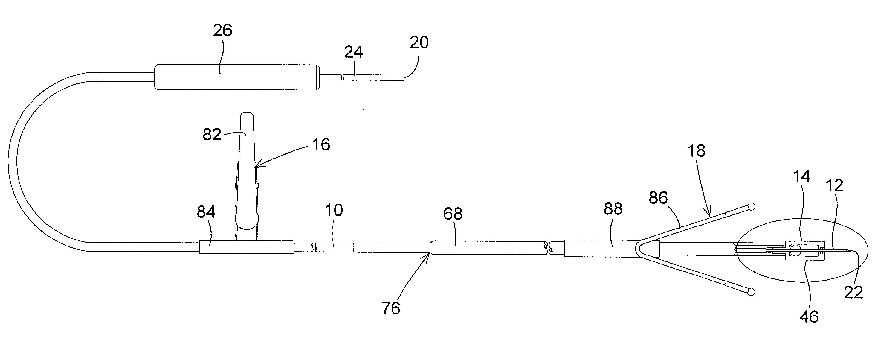
[0020]The adjustable ophthalmic surgery chandelier illuminator of the invention is basically comprised of an optic fiber 10, a needle 12, a needle housing 14, and means 16, 18 for holding the illuminator in a desired position in use. Unless set forth otherwise herein, the materials used for constructing each of these component parts of the illuminator are those typically used in the construction of prior art ophthalmic surgery illuminators.

[0021]In the preferred embodiment, the optic fiber 10 is a glass or silica optic fiber. The fiber 10 has an elongate, flexible, continuous length that extends between a proximal end 20 of the fiber and distal end 22 of the fiber. The optic fiber 10 is preferably a 25 gauge optic fiber, but could also be a 20, 23, and 27 gauge fiber. The length of the optic fiber 10 is sufficiently long to enable the illuminator of the invention to be easily manipulated by a surgeon.

[0022]A light source connector is provided on the optic fiber proximal end 20. The ...


PUM


Abstract

An adjustable ophthalmic surgery chandelier illuminator has a glass optic fiber with a conical exterior surface at its distal end that disburses illumination in the interior of the eye. The glass fiber is contained in a retractable needle that has a long, sharp beveled surface that facilitates insertion of the needle and the optic fiber into the eye, and then is retracted relative to the fiber distal end to adjust the field of illumination inside the eye.

Description

BACKGROUND OF THE INVENTION[0001]1. Field of the Invention[0002]The present invention pertains to an ophthalmic surgery apparatus that provides wide field illumination to the interior of the eye, where the degree of illumination is adjustable. More specifically, the present invention provides an ophthalmic surgery chandelier illuminator that is comprised of a glass optic fiber with a conical surface that disburses illumination in the interior of the eye, and a retractable needle mounted over the fiber conical surface. The needle has a long, sharp beveled surface that facilitates insertion of the needle and optic fiber into the eye, and can then be retracted relative to the fiber conical surface to adjust the field of illumination inside the eye.[0003]2. Description of the Related Art[0004]In the practice of ophthalmic surgery, a chandelier illuminator is a microsurgical instrument that is used to provide a wide field of illumination in the interior of the eye. Chandeliers of the pri...

Claims


Application Information

Patent Timeline
IPC IPC(8): A61B1/00
CPCA61B2019/5206A61B19/52A61B90/36A61B2090/306
Inventor SCHELLER, GREGG D.NADOLSKI, TIMOTHY J.MAIA, ANDREAWH, CARL
Owner SYNERGETICS
Learn More